Turbine blade

a turbine blade and turbine blade technology, applied in the field of turbine blades, can solve the problems of large limitation of airfoil design, weakening the flow restraint, and disturbing the flow, so as to improve the performance of the entire gas turbine, prevent flow separation, and strengthen the flow restraint

Active Publication Date: 2008-10-02
MITSUBISHI POWER LTD
View PDF4 Cites 12 Cited by
  • Summary
  • Abstract
  • Description
  • Claims
  • Application Information

AI Technical Summary

Benefits of technology

[0017]The present invention can provide an aerodynamically optimal airfoil profile that can enhance the performance of the entire gas turbine. Specifically, in the first stage turbine blade, the inter-blade passage width is formed to substantially monotonously decrease from the blade inlet toward the blade outlet. It is therefore possible to prevent flow separation from the ventral surface of the airfoil profile which otherwise occurs because the passage width monotonously increases to expand the flow, thereby weakening restraint of the flow. Thus, an aerodynamic loss can be reduced. The present invention can provide an aerodynamically optimal airfoil profile that can eliminate flow separation from the blade ventral surface, particularly, in the first stage turbine blade adopting the axial entry method.

Problems solved by technology

This will cause disturbed flows.
This imposes a large limitation on airfoil design.
The passage width monotonously increases from a blade inlet to expand flow, thereby weakening restraint of the flow.

Method used


Image

  • Turbine blade
  • Turbine blade
  • Turbine blade

Examples


Embodiment Construction

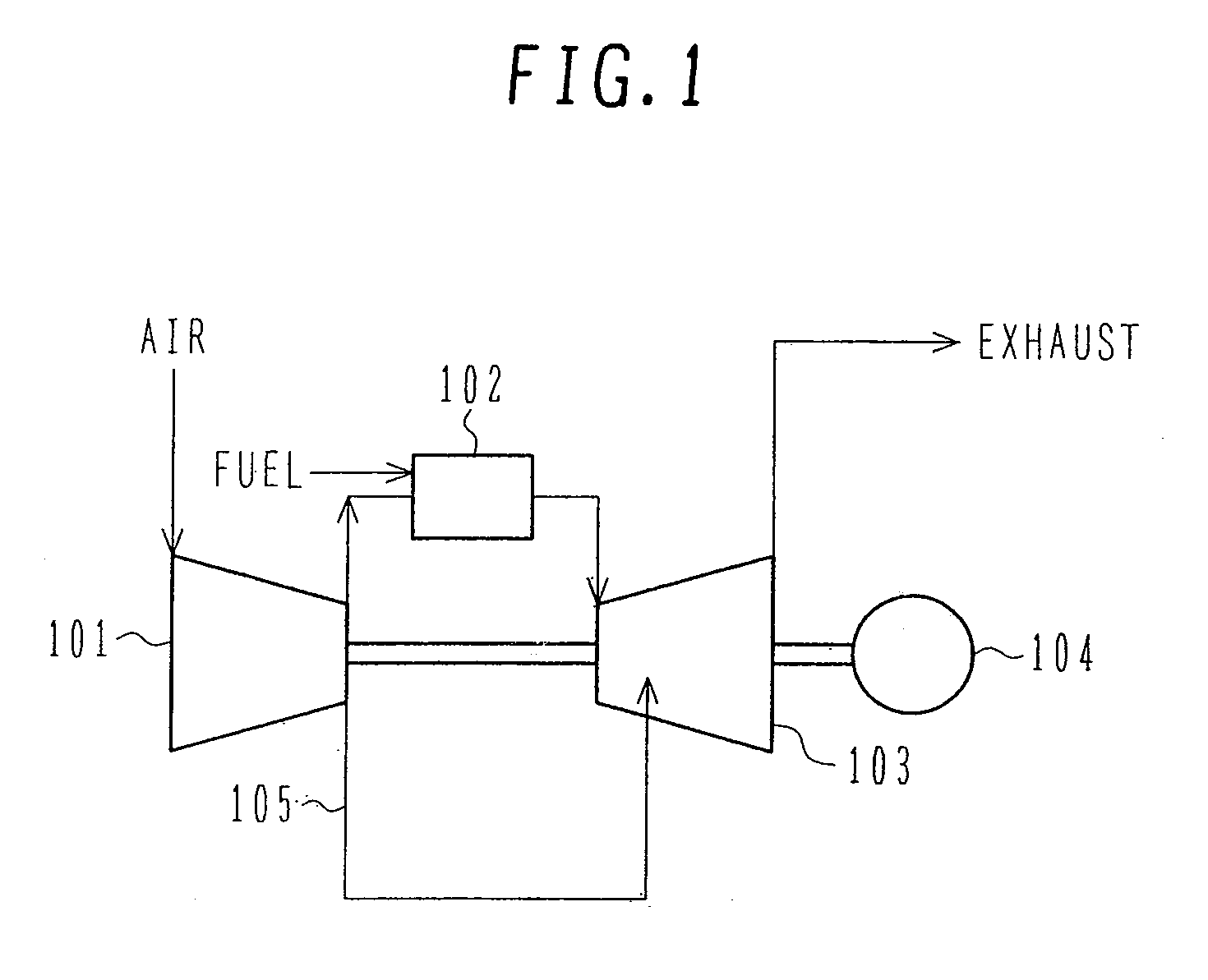
[0026]An embodiment of the present invention will hereinafter be described in detail with reference to the drawings. FIG. 1 illustrates the basic configuration of a gas turbine embodying the present invention. Air compressed by a compressor 101 is supplied to a combustor 102. The combustor 102 burns fuel fed along with the compressed air to generate drive fluid with high temperature and high pressure. A turbine 103 is driven by this drive fluid, whereby electric power is taken out from a generator 104 or a load. The drive fluid that performed its function in the turbine 103 is discharged as exhaust gas to the outside. The stator blades and blades of the turbine 103 are forcibly cooled by air 105 taken out of the compressor 101 to lower the metal temperature of blade material to an acceptable value or less.

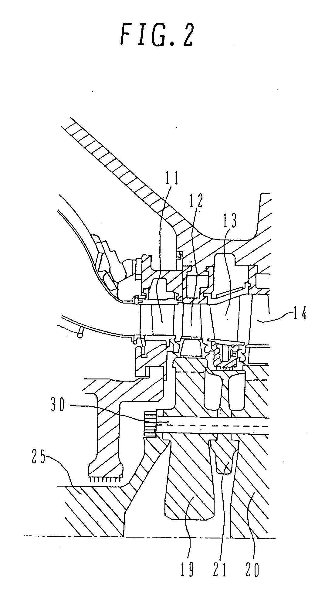
[0027]FIG. 2 is a cross-sectional view of an essential portion (blade stage portion) of the turbine 103. A mainstream gas which is the drive fluid with high temperature and high pr...


PUM


Abstract

An airfoil profile is formed such that a passage width ratio, represented in a dimensionless manner, of an inter-blade passage width of vain root cross-section to an outlet throat width substantially monotonously decreases from a blade inlet toward a blade outlet. The blade has a blade airfoil profile shape in an envelope within a range of ±2.0 mm in a direction normal to any surface location of an airfoil profile portion. The airfoil profile portion has a reference airfoil contour represented in Cartesian coordinates wherein Z is a distance representing a sectional height from a root of the airfoil profile portion. The contours represented by X and Y at each section Z are joined smoothly with one another in a blade height direction to form a complete shape of the airfoil profile portion.

Description

BACKGROUND OF THE INVENTION[0001]1. Field of the Invention[0002]The present invention relates to a turbine blade for a gas turbine and particularly to an improvement in an airfoil profile of a first stage turbine blade.[0003]2. Description of the Related Art[0004]A gas turbine of this type that has generally been adopted is configured such that working fluid compressed by a compressor is added with fuel and burned to provide high-temperature and high-pressure working fluid, which drives a turbine. The rotational energy of the turbine thus driven is usually converted into electric energy by a generator coupled to the turbine.[0005]In recent years, more expectations have been placed on improvements in the efficiency of a gas-turbine-and-steam-turbine-combined cycle. It has been intended as one of the means to further increase the temperature and pressure of the working fluid.[0006]As regards a high-temperature turbine component, particularly, a first stage turbine blade, efforts have ...

Claims


Application Information

Patent Timeline
Patent Type & Authority Applications(United States)
IPC IPC(8): F01D5/14
CPCF01D5/141F05D2250/74F05D2240/301F05D2220/3212Y02T50/60
Inventor KIZUKA, NOBUAKIMURATA, HIDETAROKUROKI, HIDETOSHINANATAKI, KENJI
Owner MITSUBISHI POWER LTD
Why Eureka
Try Eureka