
LED table lamp

Active Publication Date: 2008-10-02
PEGATRON
View PDF5 Cites 12 Cited by
  • Summary
  • Abstract
  • Description
  • Claims
  • Application Information

AI Technical Summary

Benefits of technology

[0008]According to one embodiment of the present invention, an LED table lamp capable of producing light that can light an area with a substantially uniform brightness.
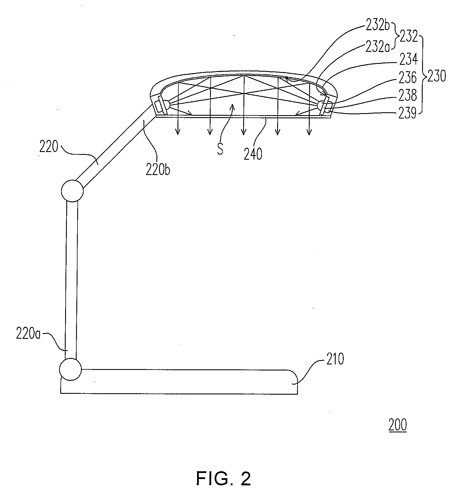
[0013]According to an embodiment of the invention, the LED light module is disposed on the side-wall of the lampshade, and the reflecting thin film with better reflectance is disposed on the top-wall of the lampshade. The light emitted from the LED light module can be reflected several times within the light emitting device by the reflecting thin film to increase the uniformity of the optical mixing. Therefore, the light emitting out of the lampshade is uniform in brightness. Thus, the LED table lamp of the invention can produce a light of uniform brightness, and therefore the disadvantages of the light causing discomfort due to light of non-uniform brightness in working area may be effectively reduced.

Problems solved by technology

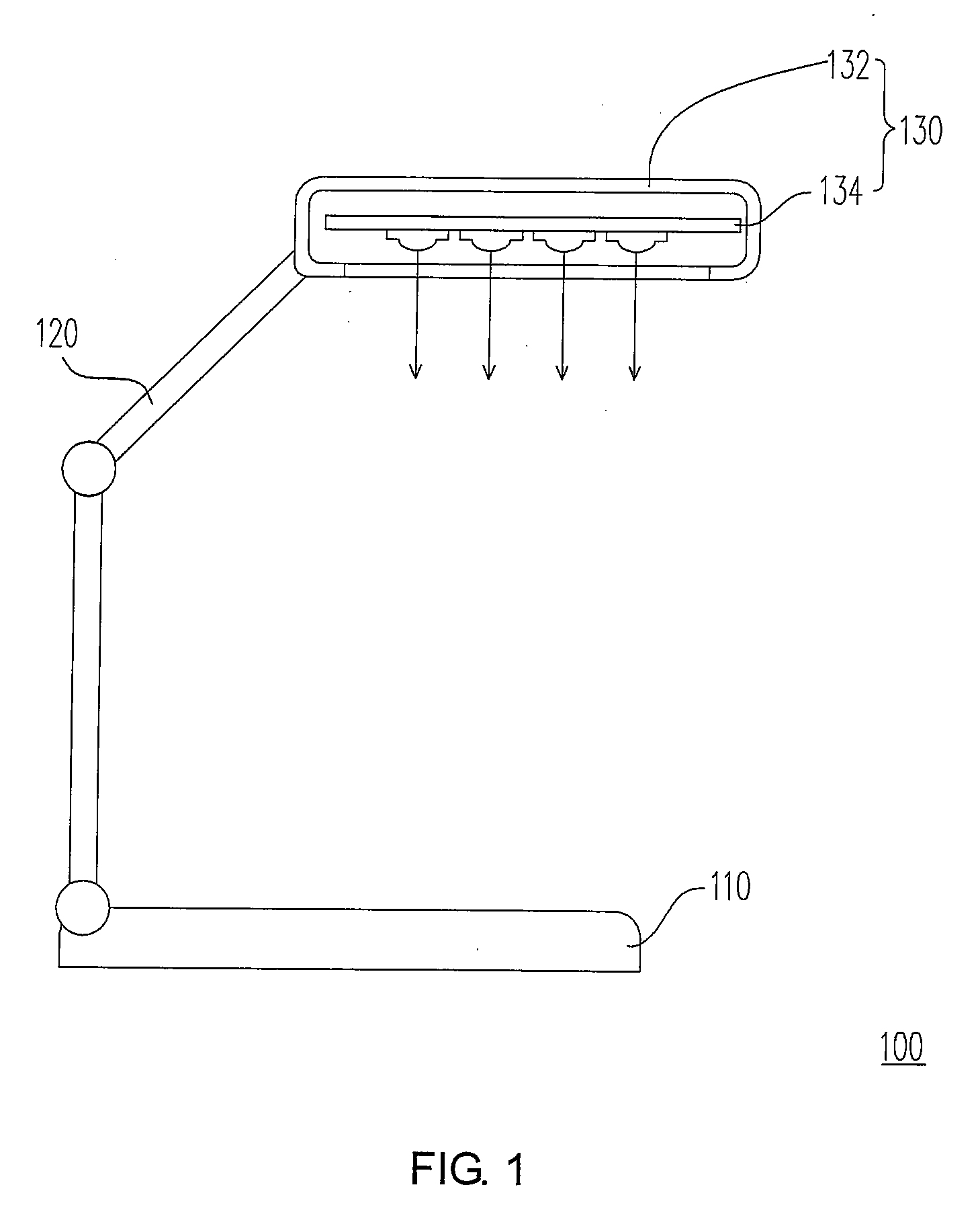
It is taken into consideration that the light emitted from the LED light module 134 is emitted directly out of the lampshade 132, which may cause discomfort to users as the light may be directly directed to the eyes while reading or working.
In addition, the lit up area, for example on a desk, generated by light from the LED light module 134 may not be uniform due to the directly lightened region and the indirectly lightened region.
Users may feel uncomfortable due to non-uniform brightness in reading or working area.

Method used


Image

  • LED table lamp
  • LED table lamp
  • LED table lamp

Examples


Embodiment Construction

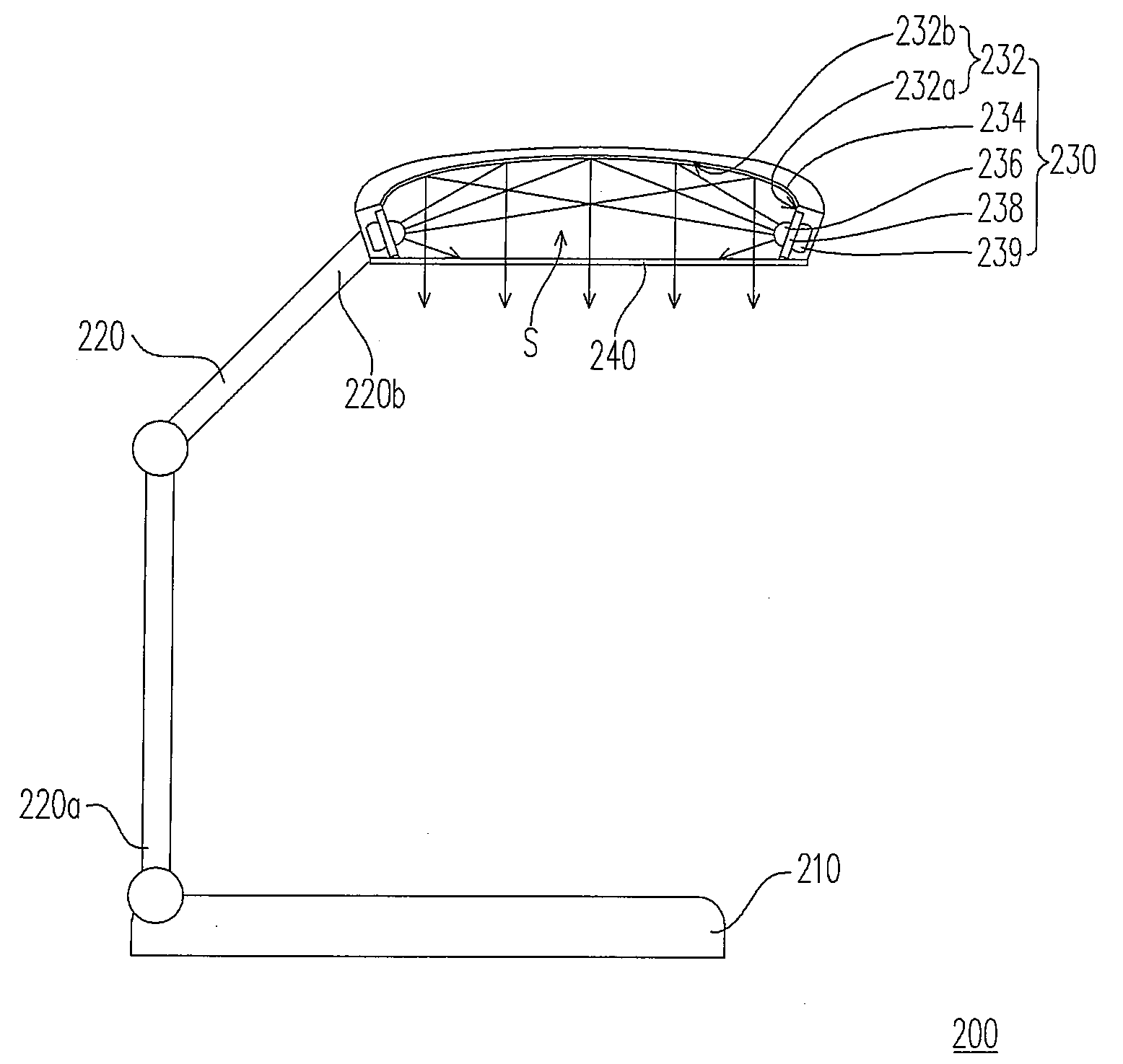
[0017]FIG. 2 is a schematic diagram showing an LED table lamp according to an embodiment of the present invention. Referring to FIG. 2, the LED table lamp 200 includes a base 210, a holder 220 and a light emitting device 230. In the present embodiment, an end 220a of the holder 220 is connected to the base 210, and the light emitting device 230 is pivotally connected to the other end 220b of the holder 220. Users can adjust the direction of the light source of the light emitting device 230 to adjust lit up area on the desk or other working stations. Hereinafter, the light emitting device 230 according to the present invention may be described in more detail as follows.

[0018]Referring to FIG. 2 again, the light emitting device 230 includes a lampshade 232, a reflecting thin film 234 and an LED light module 236. Wherein the lampshade 232 is pivotally connected to the holder 220 and has at least a side-wall 232a (FIG. 2 shows the lampshade 232 with two side-walls 232a) and a top-wall 2...


PUM


Abstract

An LED table lamp including a base, a holder, and a light emitting device is provided. An end of the holder is connected to the base, and the light emitting device includes a lampshade pivotally connected to another end of the holder, a reflecting thin film and an LED light module. The lampshade has at least a side-wall and a top-wall connected the side-wall. The reflecting thin film is disposed on the top-wall and the LED light module is disposed in the side-wall. The light emitted from the LED light module is reflected several times by the reflecting thin film to render the brightness of the light emitted out of the lampshade substantially uniform.

Description

CROSS-REFERENCE TO RELATED APPLICATION[0001]This application claims the priority benefit of Taiwan application serial no. 96110488, filed on Mar. 27, 2007. All disclosure of the Taiwan application is incorporated herein by reference.BACKGROUND OF THE INVENTION[0002]1. Field of the Invention[0003]The invention relates to a table lamp, and more particularly to a light emitting diode (LED) table lamp.[0004]2. Description of the Related Art[0005]In everyday life, people usually use a table lamp to light up dark areas indoor, such as desk, so users can read or work on the desk without worry visional degeneration due to insufficient light.[0006]In general, the light emitting diode (LED) light is more and more popular due to its small dimension and long service life. FIG. 1 is a schematic diagram showing a current LED table lamp. Referring to FIG. 1, the current LED table lamp 100 includes a base 110, a holder 120 extending from the base 110, and a light emitting device 130. The light emit...

Claims


Application Information

Patent Timeline
IPC IPC(8): F21V13/04F21V29/00F21V7/00
CPCF21S6/003F21V7/0008F21Y2101/02F21V29/006Y10S362/80F21V29/51F21Y2115/10
Inventor LIN, CHIA-TE
Owner PEGATRON
Learn More