
Monitoring and automatic control of operating parameters for a downhole oil/water separation system

a technology of oil/water separation system and operating parameters, which is applied in the direction of fluid removal, survey, borehole/well accessories, etc., can solve the problems of not providing any control or separate control of the fluid output of the dows, and achieve the effect of reducing the amount of water flow

Inactive Publication Date: 2008-10-02
SCHLUMBERGER TECH CORP
View PDF21 Cites 51 Cited by
  • Summary
  • Abstract
  • Description
  • Claims
  • Application Information

AI Technical Summary

Benefits of technology

[0012]A flow control system for use with an electric submersible pump and downhole oil water separator disposed in a wellbore according to another aspect of the invention includes a controllable valve disposed in a water outlet of the separator. At least one of a pressure sensor and a flowmeter is operatively coupled to the water outlet. A controller is in signal communication with the at least one of a pressure sensor and flowmeter and in operative communication with the valve. The controller is configured to operate the valve to maintain at least one of a selected pressure and a selected flow rate through the water outlet.
[0013]A method for operating a downhole oil water separator and electric submersible pump in a wellbore according to another aspect of the invention includes measuring a parameter related to presence of oil in a water outlet of the separator, and reducing an amount of water flow from a water outlet of the separator to an injection formation if the measured oil parameter indicates presence of oil in the separated water.
[0014]Other aspects and advantages of the invention will be apparent from the following description and the appended claims.

Problems solved by technology

'690 patent does not provide for any control over the fluid output from the DOWS or any separate control over the rate of fluid discharged from the water outlet of the DOWS.

Method used


Image

  • Monitoring and automatic control of operating parameters for a downhole oil/water separation system
  • Monitoring and automatic control of operating parameters for a downhole oil/water separation system
  • Monitoring and automatic control of operating parameters for a downhole oil/water separation system

Examples


Embodiment Construction

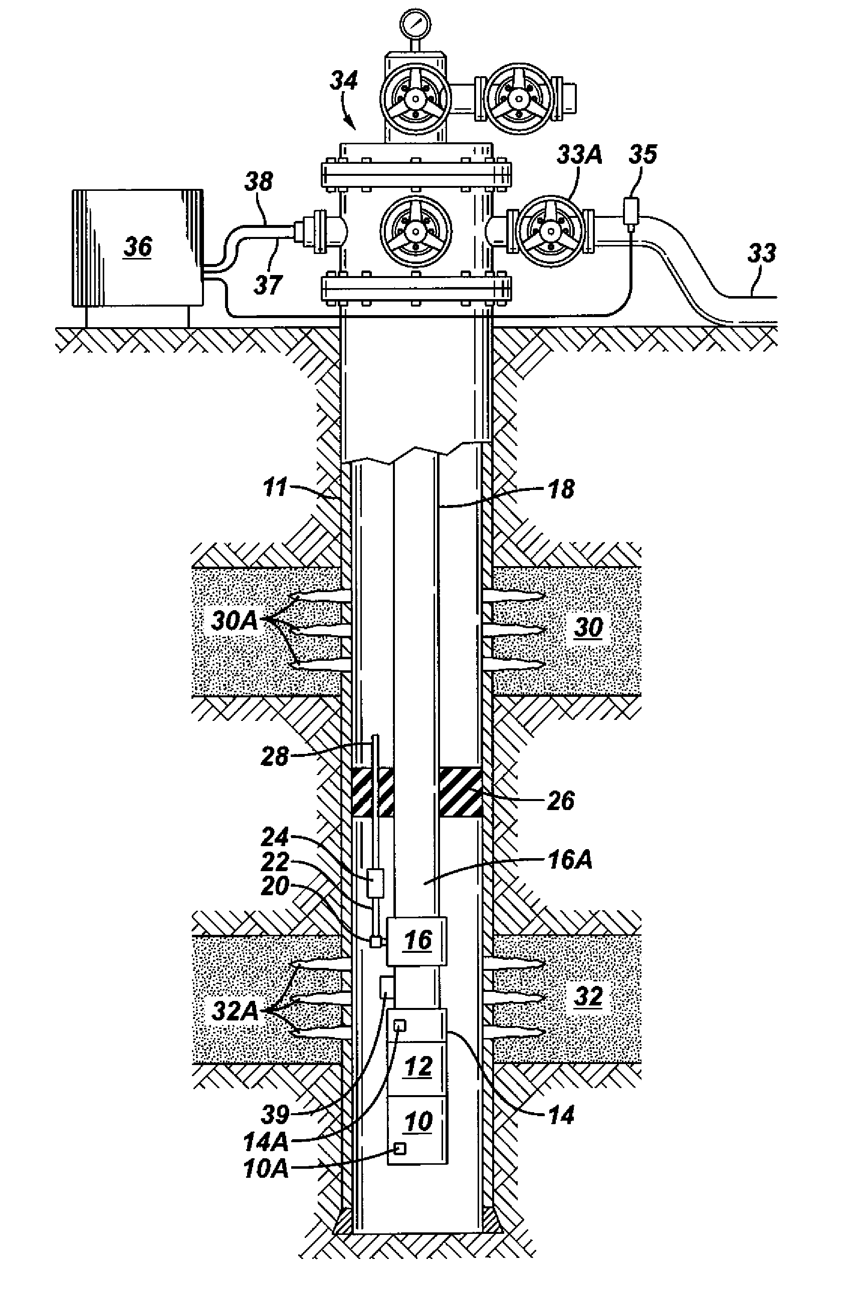
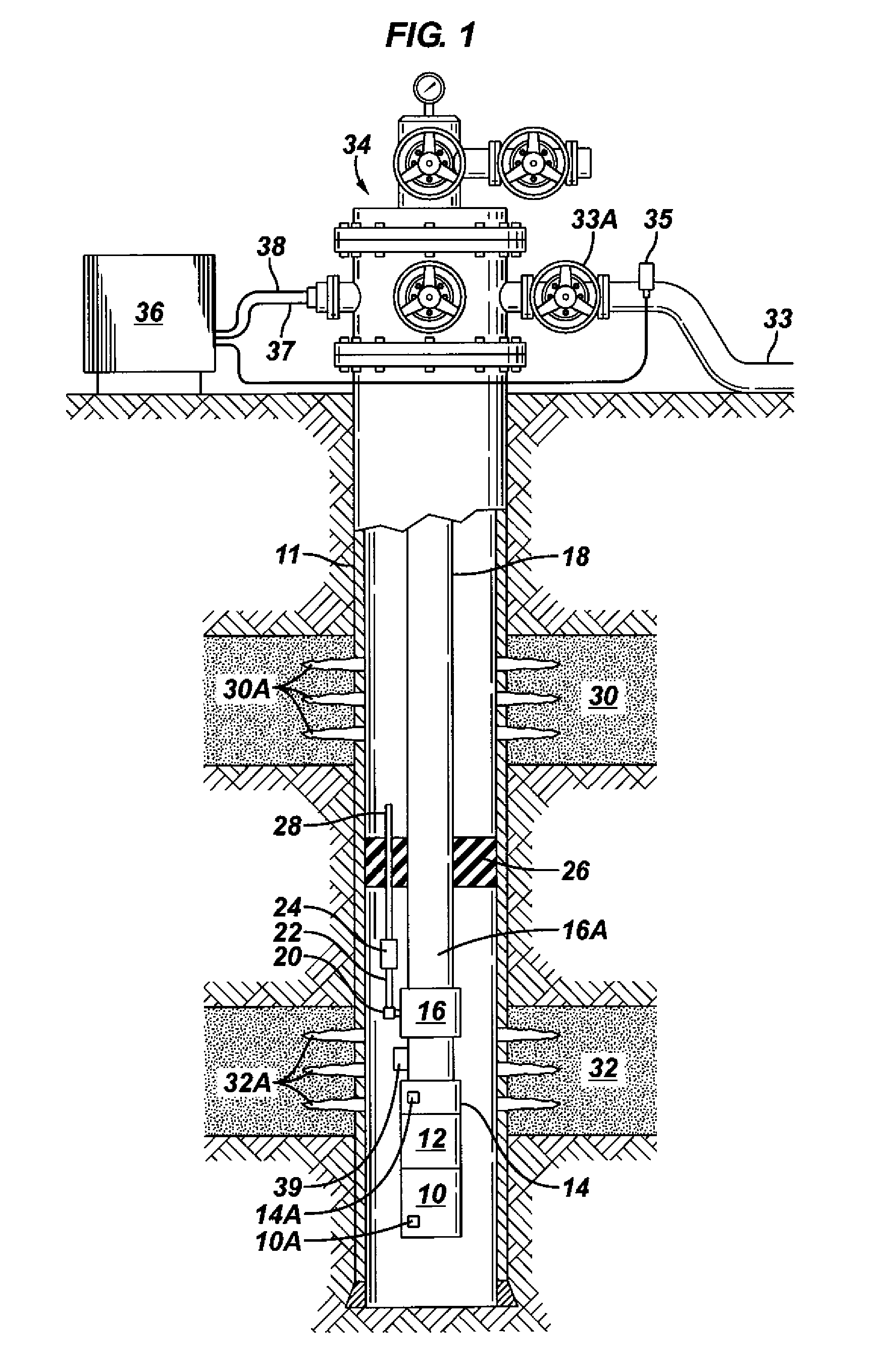
[0018]A schematic representation of an example production system including an electric submersible pump (“ESP”) coupled to a downhole oil water separator (“DOWS”) is shown in FIG. 1. A wellbore drilled through subsurface formations, including an oil producing formation 32 and a water disposal or “injection” formation 30, has a pipe or casing 11 extending from a wellhead 34 at the Earth's surface to the bottom of the wellbore. The casing 11 is typically cemented in place to hydraulically isolate the various subsurface formations and to provide mechanical integrity to the wellbore.

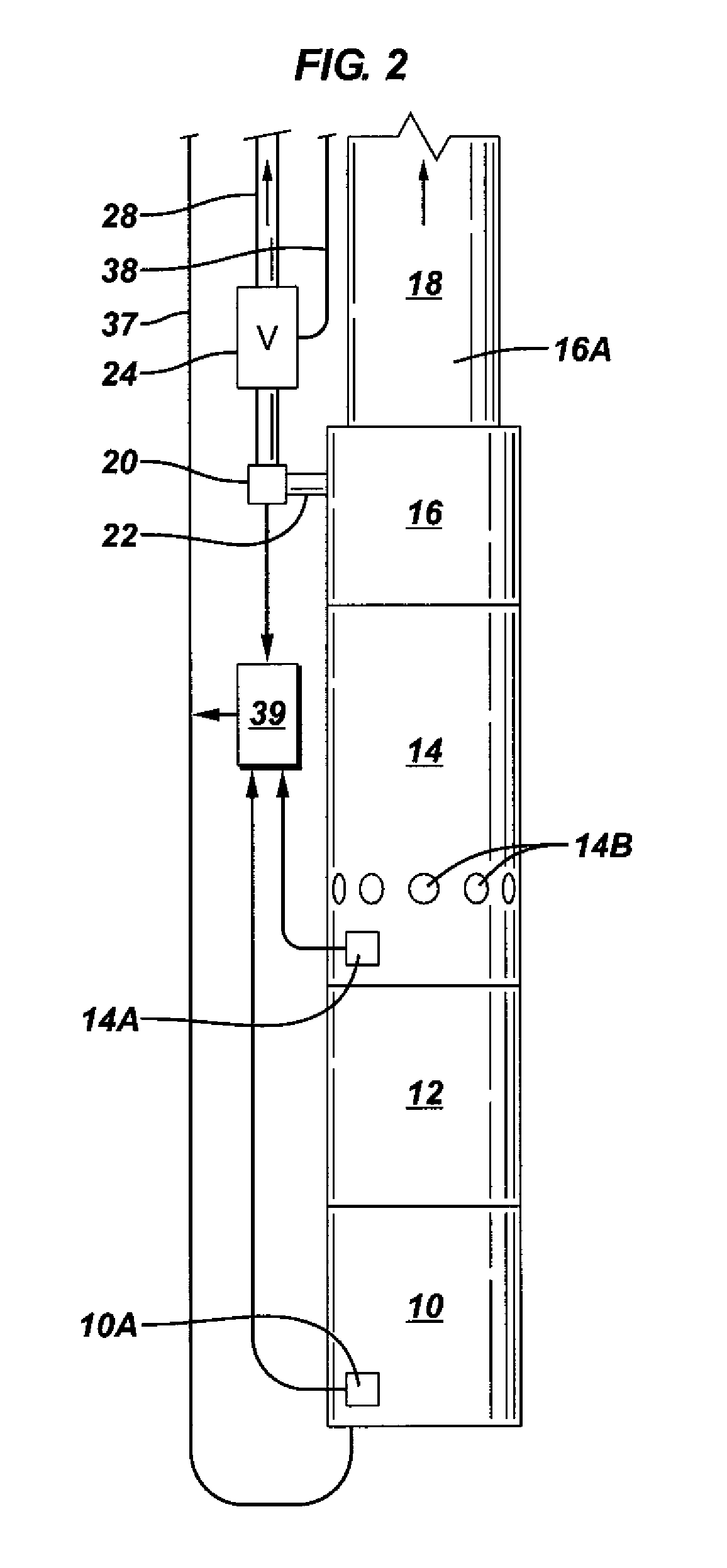
[0019]A production system including an ESP is disposed inside the casing 11 at a selected depth. The ESP typically includes an electric motor 10 such as a three-phase AC motor coupled to a protector 12. A motor sensor 10A that may include sensing elements (not shown separately) such as a three axis accelerometer may detect vibration generated by the motor 10. Measurements of acceleration (vibration) may be t...


PUM


Abstract

A method for operating a downhole oil water separator and electric submersible pump includes measuring fluid pressure proximate one of the pump intake, separator intake and a bottom of a wellbore. At least one of flow rate and pressure is measured at the separator water outlet. Pump and a water outlet restriction are controlled to maintain an optimum fluid pumping rate and an optimum injection rate of separated water. A flow control system includes a controllable valve disposed in a water outlet of the separator. At least one of a pressure sensor and a flowmeter is operatively coupled to the water outlet. A controller is in signal communication with the at least one of a pressure sensor and flowmeter and in operative communication with the valve. The controller operates the valve to maintain at a selected pressure and / or a selected flow rate through the water outlet.

Description

CROSS-REFERENCE TO RELATED APPLICATIONS[0001]Not applicable.STATEMENT REGARDING FEDERALLY SPONSORED RESEARCH OR DEVELOPMENT[0002]Not applicable.BACKGROUND OF THE INVENTION[0003]1. Field of the Invention[0004]The invention relates generally to the field of downhole oil / water separation systems. More specifically, the invention relates to automatic operation of a downhole oil / water separation system to maintain preferred system operating parameters.[0005]2. Background Art[0006]Hydrocarbon production systems known in the art include combinations of electric submersible pump (“ESP”) and downhole oil water separator (“DOWS”). In an ESP / DOWS production system, the ESP and DOWS are disposed in a wellbore drilled through subsurface formations. The wellbore typically has a steel pipe or casing disposed therein extending from the Earth's surface to a depth below the deepest subsurface formation from which fluid is to be withdrawn or injected.[0007]The ESP is typically a centrifugal pump rotat...

Claims


Application Information

Patent Timeline
Patent Type & Authority Applications(United States)
IPC IPC(8): E21B43/00
CPCE21B43/128E21B43/385E21B43/12E21B43/121E21B43/38
Inventor FIELDER, LANCE
Owner SCHLUMBERGER TECH CORP
Learn More