
Tire Inner Tube

Inactive Publication Date: 2008-09-18
BALZOWSKI JOHN
View PDF2 Cites 29 Cited by
  • Summary
  • Abstract
  • Description
  • Claims
  • Application Information

AI Technical Summary

Benefits of technology

[0011]An advantage of the invention described herein over conventional inner tube designs is that the removal of the wheel from the vehicle in order to replace the tube becomes unnecessary. With respect to most forms riding, particularly off-road riding, a flat tire is a common occurrence. Often, it is commonplace to repair a tire while out on the trail. With an inner tube of this design, it greatly reduces the number of tools that you would need to carry with you on a ride for repairs.

Problems solved by technology

A problem with inner tubes is that they can be punctured, which deflates the tube and creates a “flat tire”.
Many people encounter difficulty repairing or replacing the inner tube since it typically involves removing the wheel and possibly other parts as well.

Method used


Image

  • Tire Inner Tube
  • Tire Inner Tube
  • Tire Inner Tube

Examples


Embodiment Construction

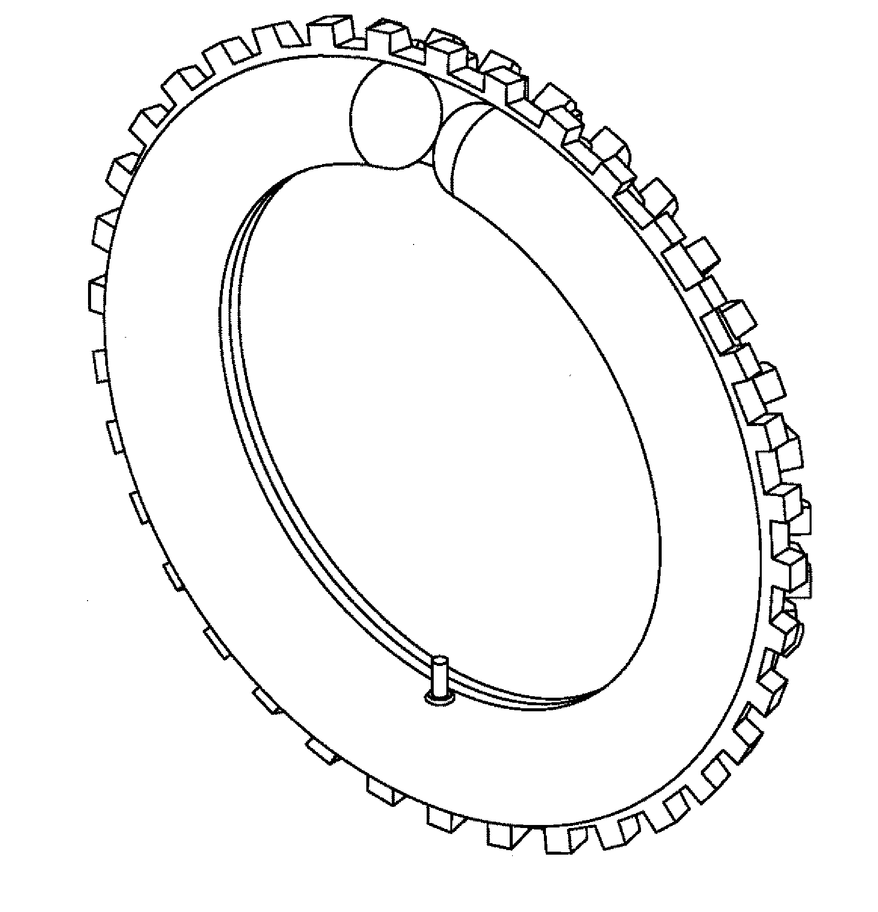
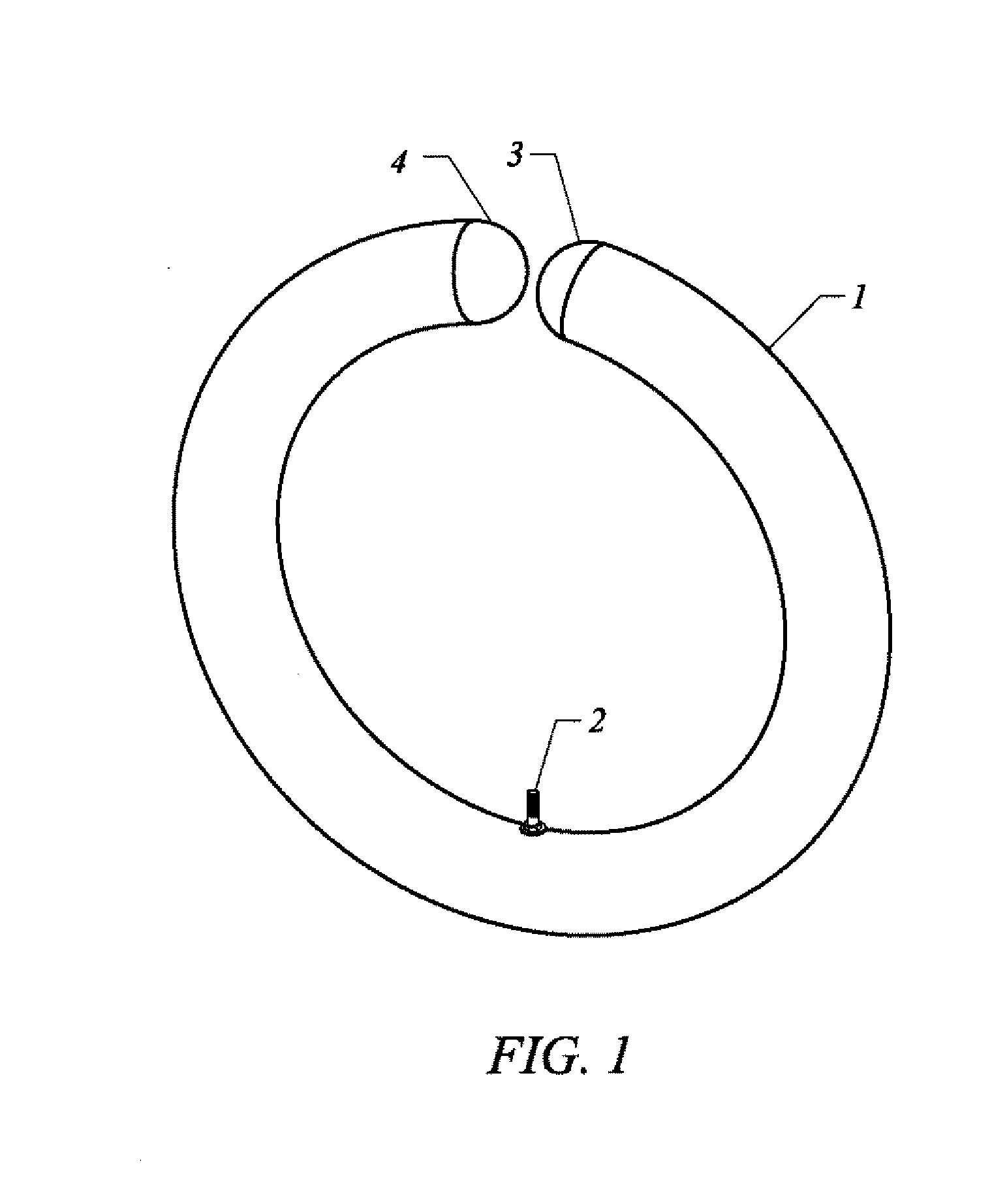
[0029]FIG. 1 shows a perspective view of an embodiment of the invention. The tube shown in this figure is molded into a circular shape that can easily fit into the inside of a tire. The ends of the tube are shown not touching each other in order to clearly illustrate that the tube is not fully contiguous. However, in practice the outside of the two ends of the tube may come into contact with each other. The ends of the tube are capped by hemispherical end pieces 3, 4 that can be molded into the tube during manufacture.

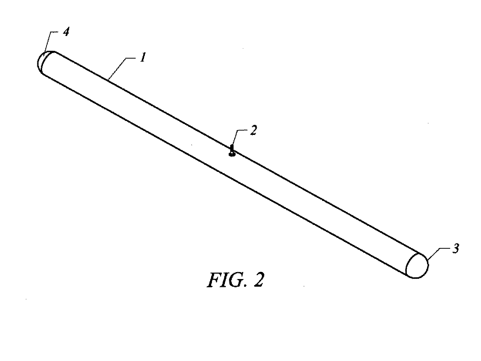
[0030]The two ends of the tube 3, 4 are separated, such that there is a first end 3 and a second end 4. Also shown is a valve stem 2, used for inflating the tube once it is installed in the tire. The location of the valve stem 2 is not a critical element of the invention, however for ease of installation, the valve stem is preferably located as shown, midway between the separation of the ends along the tube.

[0031]FIG. 1 shows an embodiment where the inner tube 1, along...


PUM


Abstract

The present invention is an inner tube apparatus, and article of manufacture, that comprises an inflatable compartment capable of surrounding a wheel. The tube comprises a first and second end that allows the user to replace the inner tube without removing the wheel, or other elements of the vehicle, for repair.

Description

I. BACKGROUND OF THE INVENTION[0001]A. Field of the Invention[0002]The invention broadly relates to inner tubes for tires. The applications include inner tubes for bicycles, motorcycles, and other wheeled devices.[0003]B. Prior Art[0004]Inner tubes for tires are well known in the art. They generally comprise inflatable rubber compartments capable of surrounding the wheel and cushioning the vehicle and occupants from vibrations and irregularities in road surfaces. Inner tubes are used in all manner of tires, including those used with motorcycles, bicycles, and automobiles. A problem with inner tubes is that they can be punctured, which deflates the tube and creates a “flat tire”. Many people encounter difficulty repairing or replacing the inner tube since it typically involves removing the wheel and possibly other parts as well. This may require the use of specialized tools and / or skills that the user lacks.[0005]It is therefore often the case that the user must bring the bicycle or ...

Claims


Application Information

Patent Timeline
IPC IPC(8): B60C5/04
CPCB60C5/10B60C5/04
Inventor BALZOWSKI, JOHN
Owner BALZOWSKI JOHN
Learn More