
Field strippable knife

Inactive Publication Date: 2008-09-18
MICROTECH KNIVES
View PDF19 Cites 43 Cited by
  • Summary
  • Abstract
  • Description
  • Claims
  • Application Information

AI Technical Summary

Benefits of technology

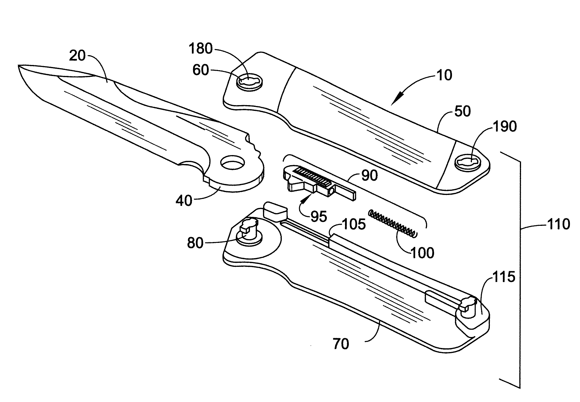
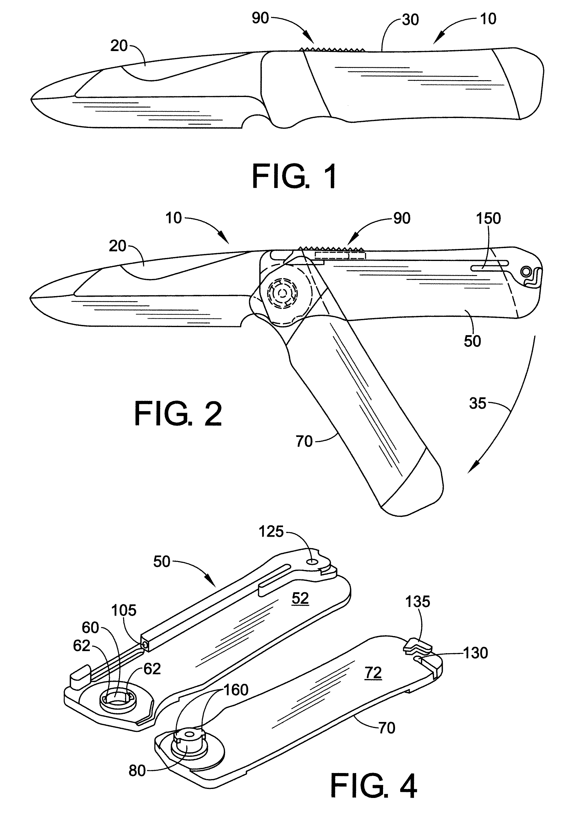
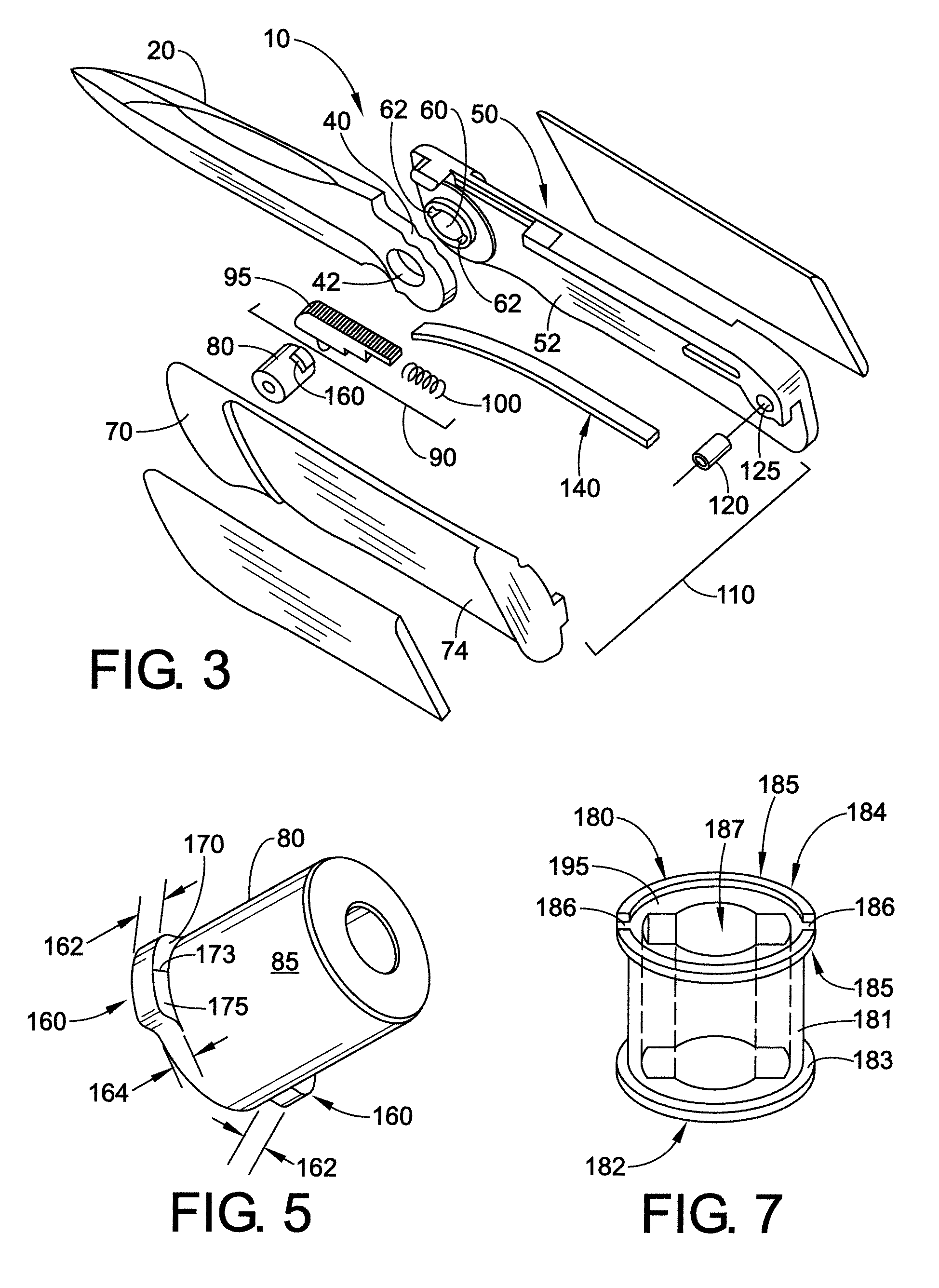
[0006]In some embodiments, the blade locking system comprises a spring and a slide, wherein the slide is positioned so as to engage two stops on the tang. The slide has a first contact end which engages the tang and a second end which engages the spring. The slide may also have a catch. The stops on the tang are located so that the blade locking system locks the blade in an open position at one stop and in a closed position between the male and female handle portions at the other stop. The tang may further comprise a smooth sliding surface between the two stops.
[0007]The lock bushing may have at least one ear and in specific embodiments has two ears. The ear may be a ramped ear. This aspect allows for tighter squeezing (a closer fit) when the male and female handle portions are engaged, preventing the blade from moving from side to side during use.
[0009]If desired, the knife may also comprise a tension lever which helps spring the blade out from its sheathed closed position to the open position.

Problems solved by technology

One problem with knives is their permanence of assembly.
Should a folding knife or other knife with moving parts get jammed or clogged with dirt, it usually cannot be disassembled without special tools.
In the field, this lack of special tools can severely hinder cleaning, use, or repair.

Method used


Image

  • Field strippable knife
  • Field strippable knife
  • Field strippable knife

Examples


Embodiment Construction

[0024]A more complete understanding of the knives and components disclosed herein can be obtained by reference to the accompanying Figures. These Figures are merely schematic representations based on convenience and the ease of demonstrating the present development and are, therefore, not intended to indicate relative size, dimensions, or location of the devices or components thereof and / or to define or limit the scope of the exemplary embodiments. Although specific terms are used in the following description for the sake of clarity, these terms are intended to refer only to the particular structure of the embodiments selected for illustration in the Figures and are not intended to define or limit the scope of the disclosure. In the Figures and the following description below, it is to be understood that like numeric designations refer to components of like function.

[0025]FIG. 1 is a side view of a first exemplary embodiment of the field-strippable knife. The knife 10 comprises a bl...


PUM


Abstract

A field-strippable folding knife which can be disassembled without special tools is disclosed. The knife has a blade a tang, and a handle. The handle comprises a male handle portion and a female handle portion which can be joined together. The tang may have two stops. The stops are engaged by a blade locking system to fix the blade in an open position and a closed position.

Description

BACKGROUND[0001]This application relates broadly to folding knives. Knives that have blades which move from a closed position to an open position are well known. In a folding knife, the blade pivots about an axis normal to a common plane of the handle and blade between a closed position within the handle through an arc to an open position external of the handle. In the open position, a lock prevents the blade from pivoting on the axis during use.[0002]One problem with knives is their permanence of assembly. Should a folding knife or other knife with moving parts get jammed or clogged with dirt, it usually cannot be disassembled without special tools. In the field, this lack of special tools can severely hinder cleaning, use, or repair. A need exists for a knife which can be field-stripped without need of special tools.BRIEF DESCRIPTION[0003]Disclosed herein, in various embodiments, is a field strippable knife. The knife comprises a blade; a tang; and a handle. The tang is preferably...

Claims


Application Information

Patent Timeline
IPC IPC(8): B26B1/04
CPCB26B5/00B26B1/048
Inventor MARFIONE, ANTHONY L.MARFIONE, ANTHONY G.
Owner MICROTECH KNIVES
Learn More