
Automatic Surface-Scanning Method and System

a surface scanning and automatic technology, applied in the direction of distance measurement, process and machine control, instruments, etc., can solve the problems of accumulating errors over time, robots by integrating a series of relative positions, and not being suitable for mass production equipment creation

Inactive Publication Date: 2008-09-11
WANY
View PDF15 Cites 38 Cited by
  • Summary
  • Abstract
  • Description
  • Claims
  • Application Information

AI Technical Summary

Benefits of technology

"The patent aims to create systems and procedures for using low-cost sensors to navigate complex surfaces. The technical effect of this invention is to overcome the limitations of current position sensors and provide a more accurate and reliable method for navigating complex surfaces."

Problems solved by technology

Now given their purchase price, such absolute position sensors are not very suitable for the creation of equipment designed for mass production.
However the systems calculating the location of a robot by integrating a series of relative positions have the disadvantage of accumulating errors over time.
The result is that after a certain distance, the absolute location includes an error arising mainly from integrating noise from the sensors used.
Finally, it should be noted that low-noise sensors do exist but given their purchase price, these sensors are not very suitable for the creation of equipment designed for mass production.

Method used


Image

  • Automatic Surface-Scanning Method and System
  • Automatic Surface-Scanning Method and System
  • Automatic Surface-Scanning Method and System

Examples


Embodiment Construction

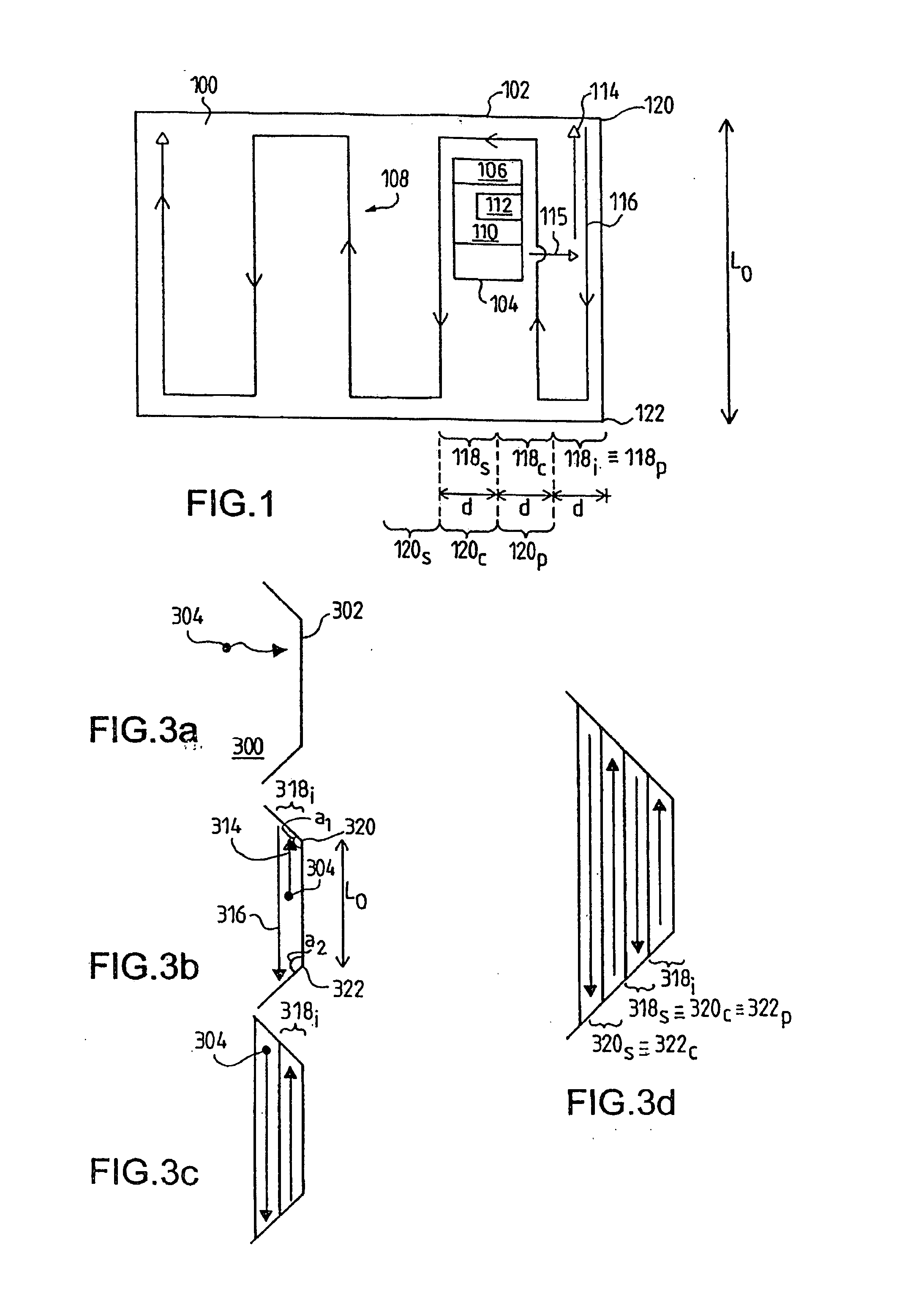
[0107]In the description of the invention given below, we are considering a complex surface 100 (FIG. 1), that is one which, for example, may include irregularities and / or variations of gradient, and delimited at least partially by a physical barrier 102 such as a wall or a gap or change of direction in the complex surface.

[0108]The nature of this surface, which can be flat and / or warped, varies as a function of the application in which a robot 104 according to the invention is used. Thus, such an application can relate to a robot which is used to treat wild or cultivated land, to a vacuum-cleaning robot, to a robotic lawn mower, to a robot employed to wash horizontal or inclined walls, particularly of the glazed or ceiling or roof type, or indeed to a robot for the decontamination of complex contaminated surfaces.

[0109]Furthermore, this surface can include one or more obstacles which, similarly to the physical barrier, limit the movement of the robot requiring to scan this surface,...


PUM


Abstract

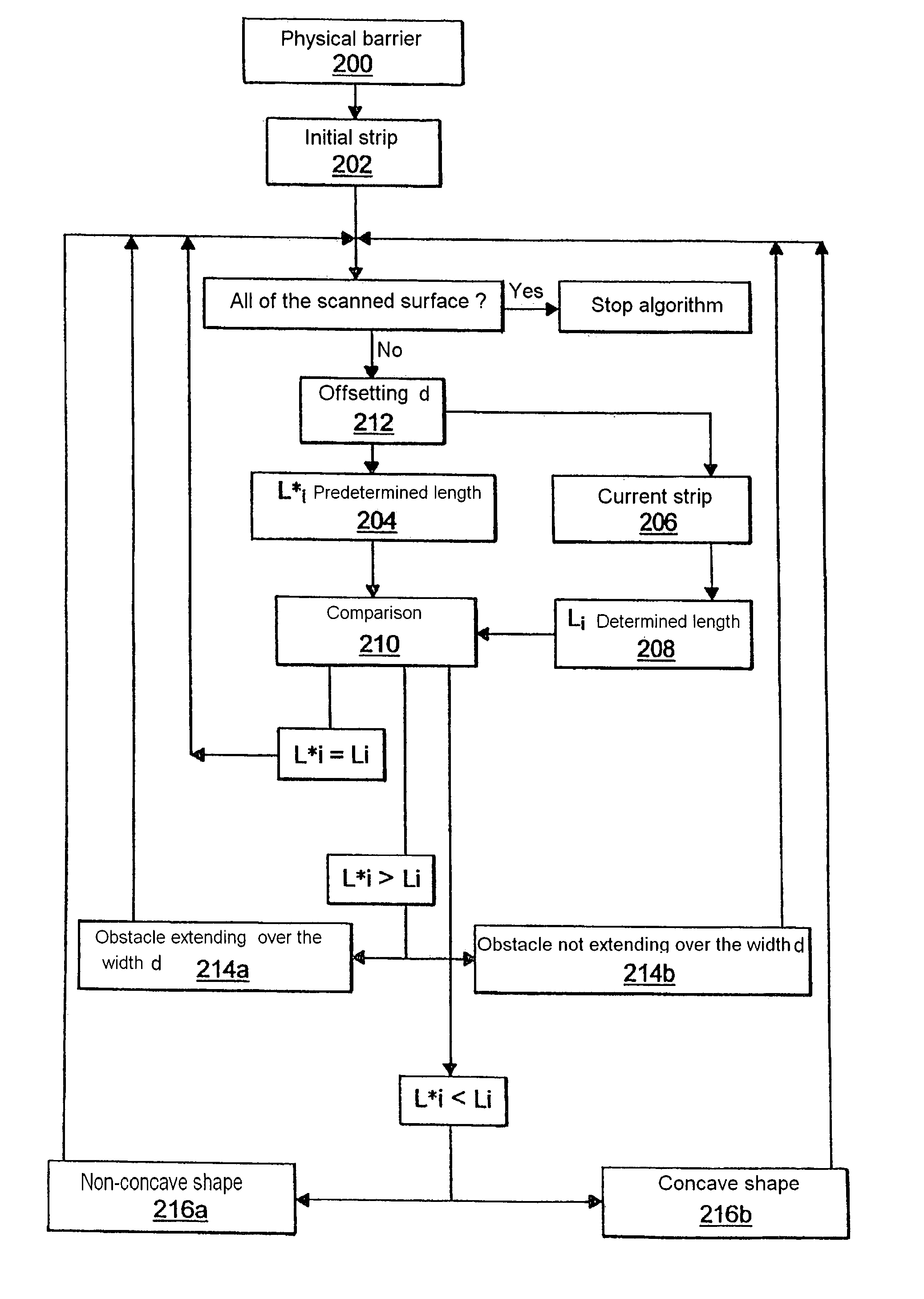
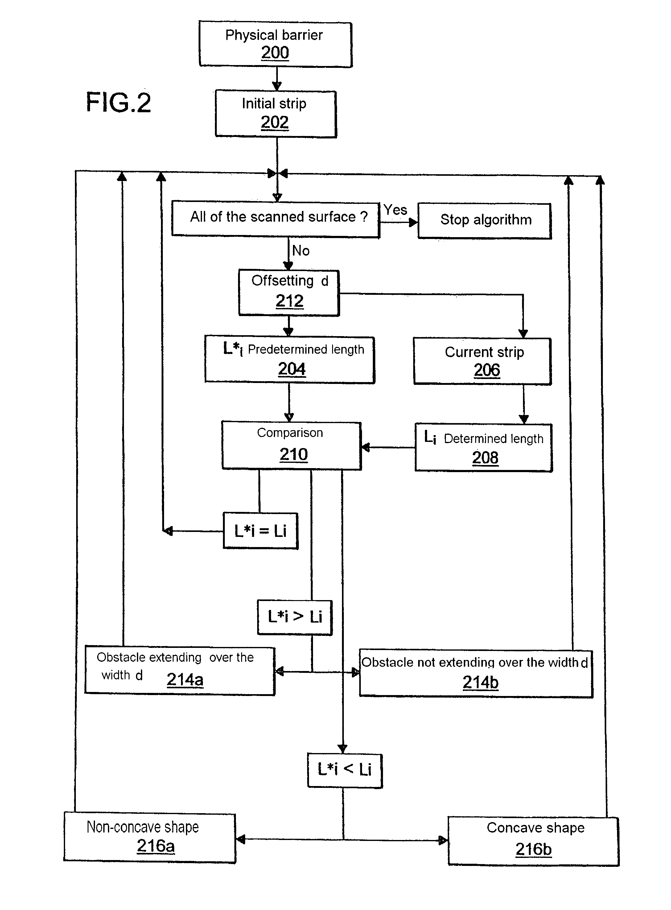
The invention relates to a method of scanning a complex surface (100) defined at least partially by a physical barrier (102) and / or obstacles. The inventive method comprises: a step which is used to detect said physical barrier (102) and / or obstacles, and an initial step which is intended to calculate the length (L0) of an initialisation strip. The method involves the use of an iterative process consisting in first travelling along the initialisation strip and continuing with other strips known as the preceding strip (118p, 120p), the current strip (118c, 120c) and the next strip (118s, 120s), the first preceding strip (118p) being formed by the initialisation strip (118i), such as to scan the complex surface.

Description

AREA OF THE INVENTION[0001]This present invention concerns the area of robotics. More particularly it concerns a process and a system implemented by a mobile robot designed to scan a complex surface, that is to traverse this complex surface in an independent manner in a sufficiently exhaustive manner to effect a treatment of the latter during this journey.THE PROBLEM, AND PRIOR ART[0002]In many applications, particularly in the area of domestic and garden equipment, it is necessary to design independent equipment, such as vacuum cleaning robots, known in what follows as mobile robots, capable of traversing, in a virtually exhaustive manner, a complex surface that includes obstacles (such as the floor of a furnished room).[0003]To this end, we are familiar with systems and procedures for the traversing of complex surfaces employing sensors used to scan the environment (particularly the walls of the room and the furniture located within it) and to record the relative position of the r...

Claims


Application Information

Patent Timeline
Patent Type & Authority Applications(United States)
IPC IPC(8): G06F17/00G05D1/02
CPCG05D1/0219G05D1/0242G05D2201/0203G05D1/0274G05D1/0272
Inventor LAVAREC, ERWANN
Owner WANY
Learn More