
Image sensor with extended dynamic range

a dynamic range, image sensor technology, applied in the field of image sensors, can solve problems such as difficult recognition of objects in captured images, and achieve the effect of extending the dynamic range of the main pixel

Inactive Publication Date: 2008-09-04
SAMSUNG ELECTRONICS CO LTD
View PDF2 Cites 67 Cited by
  • Summary
  • Abstract
  • Description
  • Claims
  • Application Information

AI Technical Summary

Benefits of technology

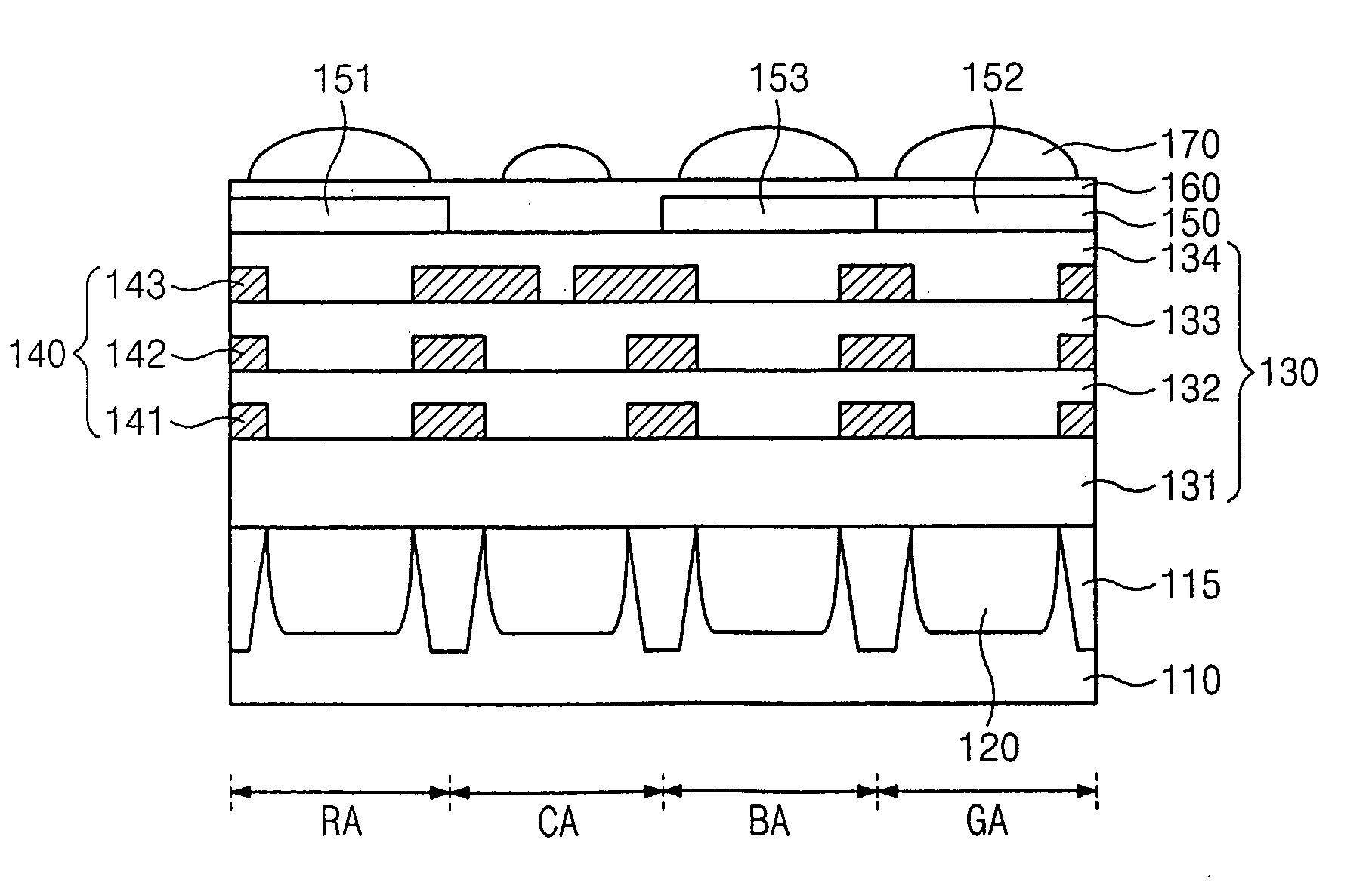
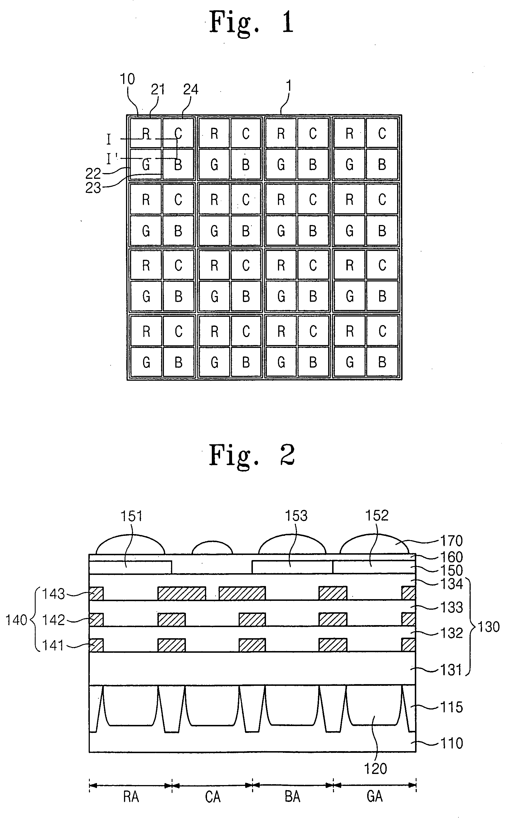
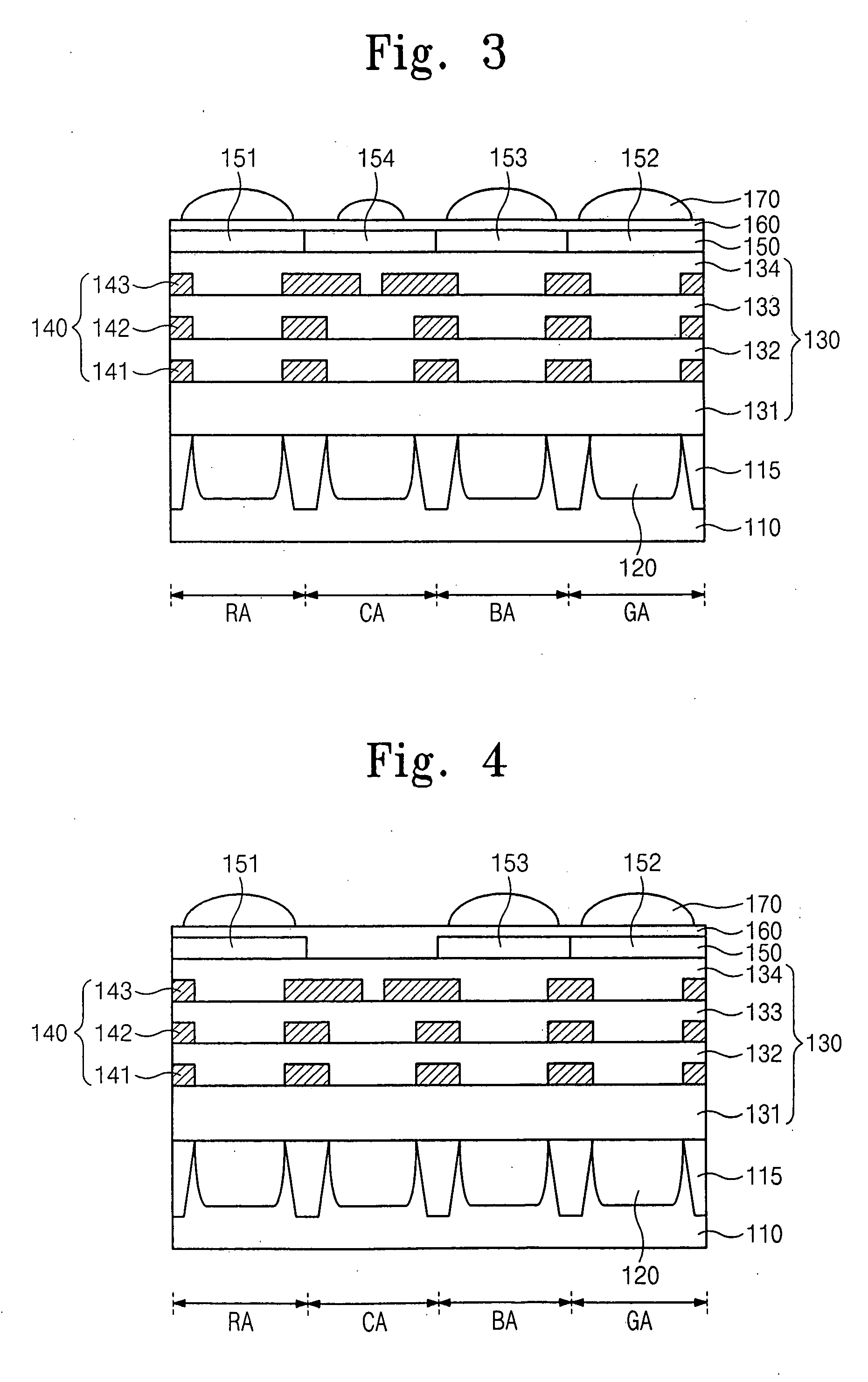
The present invention provides an image sensor with compensation sub-pixels that extend the dynamic range of the image sensor. The image sensor includes a first sub-pixel, a second sub-pixel, and an image processor. The image processor adds a change in the second image signal from a saturation level to the first image signal to generate a final image signal when the first sub-pixel is saturated. The second sub-pixel acts as a compensation sub-pixel for extending the dynamic range of the main pixel. The image sensor can effectively capture objects illuminated with high light intensity.

Problems solved by technology

For example, when a bright object is shot at night, the object in the captured image may be difficult to recognize when the image sensor does not have an extended dynamic range.

Method used


Image

  • Image sensor with extended dynamic range
  • Image sensor with extended dynamic range
  • Image sensor with extended dynamic range

Examples


Embodiment Construction

[0031]Preferred embodiments of the present invention are now described below in more detail with reference to the accompanying drawings. The present invention may, however, be embodied in different forms and should not be construed as being limited to the embodiments set forth herein. Rather, these embodiments are provided so that this disclosure will be thorough and complete, and will fully convey the scope of the present invention to those skilled in the art.

[0032]Terms used herein such as ‘first’ and ‘second’ are used to indicate various elements, but the elements should not be limited by these terms. These terms are used to only discriminate the elements from one another. In the figures, the dimensions of layers and regions are exaggerated for clarity of illustration.

[0033]It will also be understood that when a layer (or film) is referred to as being ‘on’ another layer or substrate, it can be directly on the other layer or substrate, or intervening layers may also be present. Fu...


PUM


Abstract

An image sensor includes a first sub-pixel, a second sub-pixel, and an image processor. The first sub-pixel generates a first image signal with a first sensitivity, and the second sub-pixel generates a second image signal with a second sensitivity less than the first sensitivity. The image signal processor adds a change in the second image signal from a saturation level to the first image signal to generate a final image signal when the first sub-pixel is saturated.

Description

[0001]This application claims priority under 35 USC § 119 to Korean Patent Application No. 2007-0002978, filed on Jan. 10, 2007 in the Korean Intellectual Property Office, the disclosure of which is incorporated herein in its entirety by reference.BACKGROUND OF THE INVENTION[0002]1. Field of the Invention[0003]The present invention relates generally to image sensors, and more particularly, to an image sensor having an extended dynamic range.[0004]2. Background of the Invention[0005]An image sensor converts an image into electrical signals, and is widely used for many applications such as in digital cameras. The image sensor includes a pixel array, i.e., a plurality of pixels arranged in a matrix configuration. Each pixel includes a photodiode for generating signal charges from incident photons, and includes devices for transferring and outputting the signal charges generated by the photodiode.[0006]The quality of the image sensor is indicated by many characteristics, such as a dynam...

Claims


Application Information

Patent Timeline
Patent Type & Authority Applications(United States)
IPC IPC(8): H04N3/14
CPCH04N9/045H04N5/35563H04N25/585H04N23/84H04N25/134H04N25/133H01L27/14621H01L27/14627H01L27/14603H04N25/00H04N23/10
Inventor HONG, JONG-WOOKPARK, CHANJUNG, SANG-IL
Owner SAMSUNG ELECTRONICS CO LTD
Learn More