
Switchgear

Inactive Publication Date: 2008-08-28
HITACHI LTD
View PDF5 Cites 7 Cited by
  • Summary
  • Abstract
  • Description
  • Claims
  • Application Information

AI Technical Summary

Benefits of technology

[0009]The present invention has been made based on the above-mentioned facts, and aims at providing a switchgear capable of improving interrupting capability while eliminating instability of electrical insulation ability due to floating of potential of the non-earthed metal vacuum chamber.
[0013]According to the present invention, it is possible to improve interrupting ability of the switchgear by controlling potential of the non-earthed metal vacuum chamber, because instability of electric insulating ability is eliminated.

Problems solved by technology

Further, there is instability of electrical insulation strength that is due to floating of the potential of the non-earthed metal vacuum chamber.
Thus, there was a problem that the current interrupting ability could not be increased.

Method used


Image

  • Switchgear
  • Switchgear
  • Switchgear

Examples


first embodiment

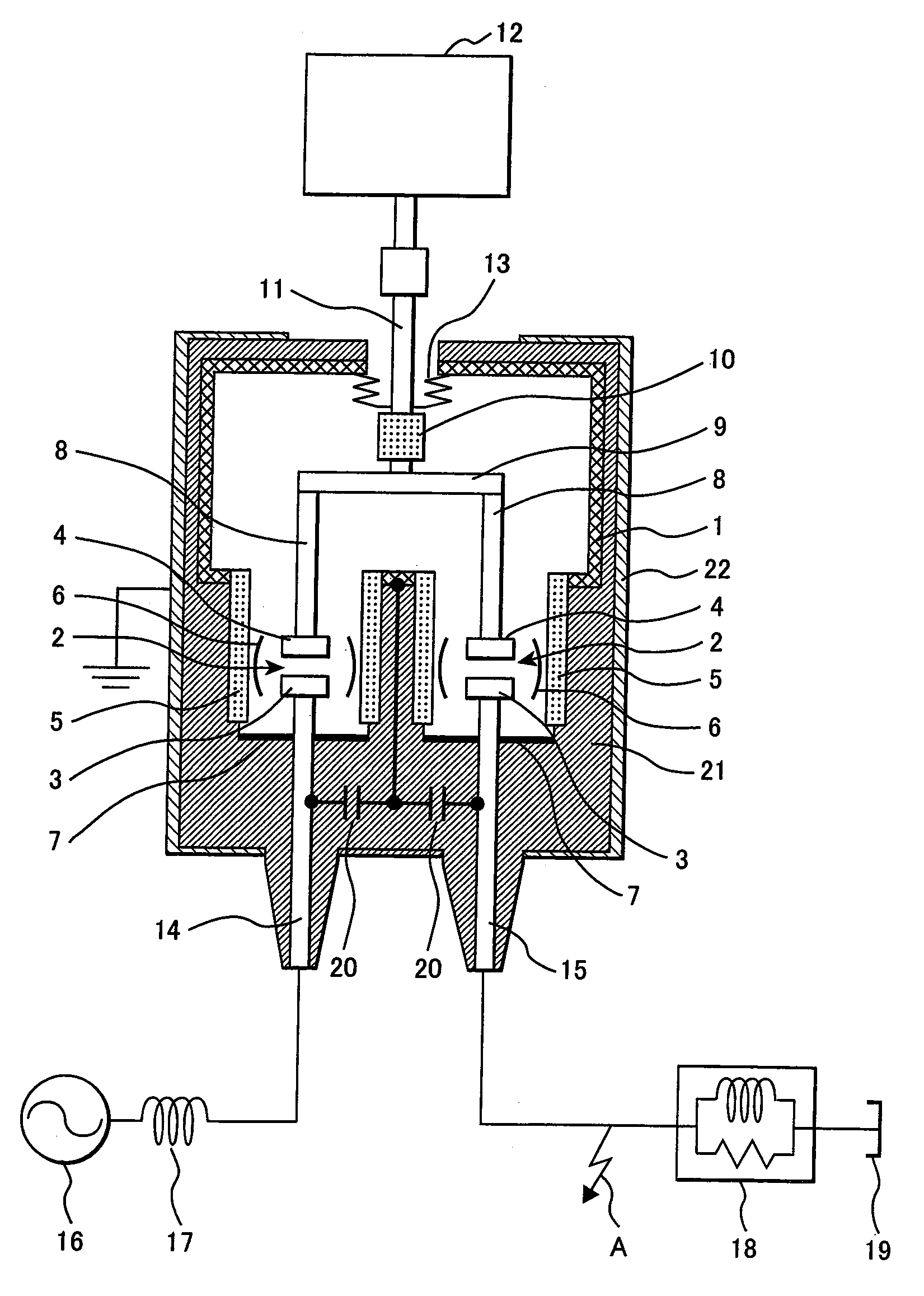
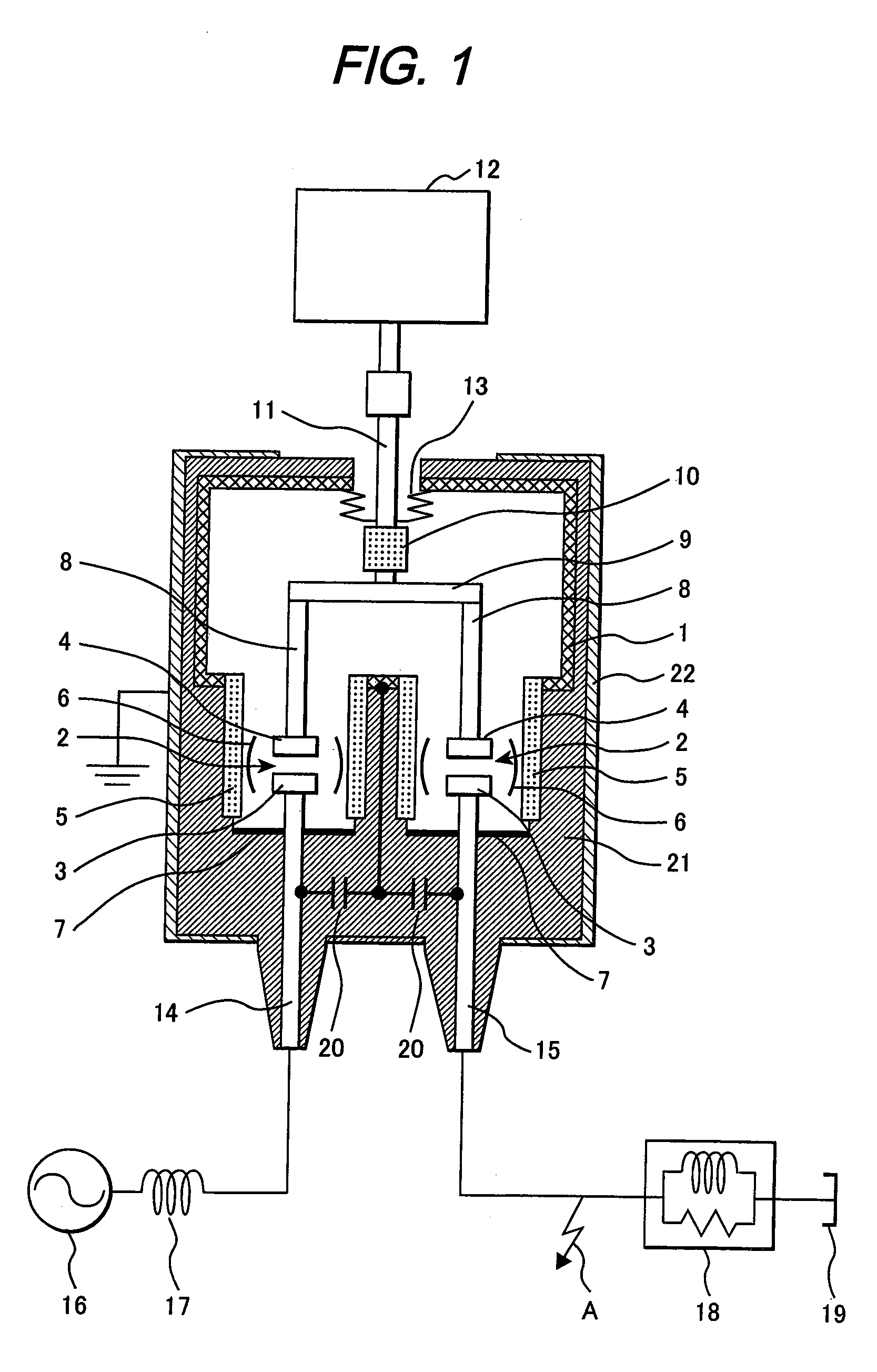
[0023]FIG. 1 shows a vertical cross sectional view of a switchgear of the present invention. In FIG. 1, two interrupters 2 are disposed in a non-earthed metal vacuum chamber 1. Each interrupter 2 is provided with a fixed contact 3 and a moving contact 4. Each of the interrupter 2 is disposed in a dielectric cylinder 5. Each dielectric cylinder 5 is provided with an arc shield 6 with a corresponding interrupter therein. A terminal plate 7 is disposed at the fixed contact side of the dielectric cylinder 5.

[0024]The moving contacts 4 of the interrupters 2 are supported by respective moving holders 8, which are electro-conductive. The moving holders 8 are connected by means of a connecting conductor 9 to each other. The connecting conductor 9 is connected to an operating rod 11 protruding from the non-earthed metal vacuum chamber 1 through an insulator 10 located in the vacuum chamber. The operating rod 11 is connected to an operating device. A penetrating portion of the operating rod 1...

third embodiment

[0043]FIG. 4 shows a vertical cross sectional view of a switchgear of the present invention. In FIG. 4, the same reference numerals as in FIG. 1 denote the same components as in FIG. 1; detailed explanations thereof are omitted.

[0044]In this embodiment, the impedance 20 such as non-linear resistor 20C is connected between the circuit terminals, i.e. bus terminal 14 and the load terminal 15.

[0045]According to this embodiment, since potential stresses imparted on each interrupter 2 does not exceed a varister voltage of the non-linear resistor 20C, it is possible to prevent a progress of electrical breakdown of one pole to a two pole series electrical breakdown between the circuit terminals in the same phase, the breakdown at the contacts of one interrupter 2 being followed by another breakdown triggered at the other contacts of the other interrupter 2. Accordingly, the advantages of the above-described embodiments are obtained.

fourth embodiment

[0046]FIG. 5 shows a vertical cross sectional view of the switchgear of the present invention. In this figure, the same reference numerals as those in FIG. 1 denote the same components as in FIG. 1; detailed explanations thereof are omitted. In this embodiment, impedance such as non-linear resistor 20D is connected between the non-earthed metal vacuum chamber 1 and the earth layer 22. This condenser is constituted by a non-linear resistance 20D.

[0047]According to this embodiment, even if a ground voltage of the non-earthed metal vacuum chamber 1 increases due to continued application of unipolar voltage, the potential does not exceed the varister voltage of the non-linear resistance 20D. As a result, the withstanding resistance becomes stabilized.

[0048]As same as in the embodiments having been described, the switchgear can be downsized and its cost can be lowered.


PUM


Abstract

A switchgear having interrupters wherein at least two moving contacts are capable of being open and close with respect to respective fixed contacts. The switchgear comprises a non-earthed metal vacuum chamber enclosing the interrupters therein, a connection conductor for connecting the moving contacts, an operating rod connected to the connecting conductor by means of an insulator and protruding from the non-earthed metal vacuum chamber, a sealing means for sealing the protrusion of the operating rod at the non-earthed metal vacuum chamber, circuit terminals protruding from the non-earthed vacuum chamber, an earth layer surrounding an outer periphery of the insulating mold, and apotential control means. The control means for controlling the potential of the non-earthed metal vacuum chamber is connected between the circuit terminals and is connected to the non-earthed metal vacuum chamber at the intermediate point of the potential control means.

Description

[0001]This application is a continuation application of U.S. application Ser. No. 11 / 748,049, filed May 14, 2007, the entirety of which is incorporated herein by reference.CLAIM OF PRIORITY[0002]The present application claims for priority from Japanese application serial No. 2006-135243, filed on May 15, 2006, the content of which is incorporated by reference into this application.FIELD OF THE INVENTION[0003]The present invention relates to a switchgear having a plurality of interrupters, and more particularly to a switchgear that is capable of eliminating instability of electrical insulating ability of a non-earthed metal vacuum chamber having the plurality of interrupters therein.RELATED ART[0004]As an example of a conventional switchgear, there has been known a two-poles vacuum circuit breaker wherein two pairs of interrupters connected in series are opened simultaneously to interrupt current. In the switchgear, the pairs of the interrupters are arranged in parallel in a metal va...

Claims


Application Information

Patent Timeline
IPC IPC(8): H01H33/66
CPCH01H1/2066H01H33/24H01H33/66207H01H33/16H01H2033/66284H01H2033/6668H01H2033/6623
Inventor SATO, TAKASHIMORITA, AYUMUKOBAYASHI, MASATOKAJIWARA, SATORU
Owner HITACHI LTD
Learn More