
Simultaneous tubular handling system

a tubular and simultaneous technology, applied in the direction of rotary drilling, drilling pipes, borehole/well accessories, etc., can solve the problems of increased cost, increased depth, and longer drilling time, and achieve the effect of reducing the number of articulated motions

Active Publication Date: 2008-08-28
FRIEDE & GOLDMAN UNITED BV
View PDF99 Cites 105 Cited by
  • Summary
  • Abstract
  • Description
  • Claims
  • Application Information

AI Technical Summary

Problems solved by technology

The increase in depth translates into longer drilling time, and increased cost.
The cost to operate such rigs is already substantial (rental rates for some offshore rigs can exceed U.S. $400,000 to $500,000 per day).
Additional tubulars must be moved from a storage rack and connected with the upper end of the tubular string, which may cause significant delay in drilling.
The disadvantages of the above tubular handling methods and systems include significant human physical contact with the tubulars and lifting equipment at numerous times and locations, which can result in costly delay or possible injury.
The alignment and transfer operations are lengthy and complex.
The paths of the tubulars in the offline stand building are not fully restricted, which creates delay and safety hazards.

Method used


Image

  • Simultaneous tubular handling system
  • Simultaneous tubular handling system
  • Simultaneous tubular handling system

Examples


Embodiment Construction

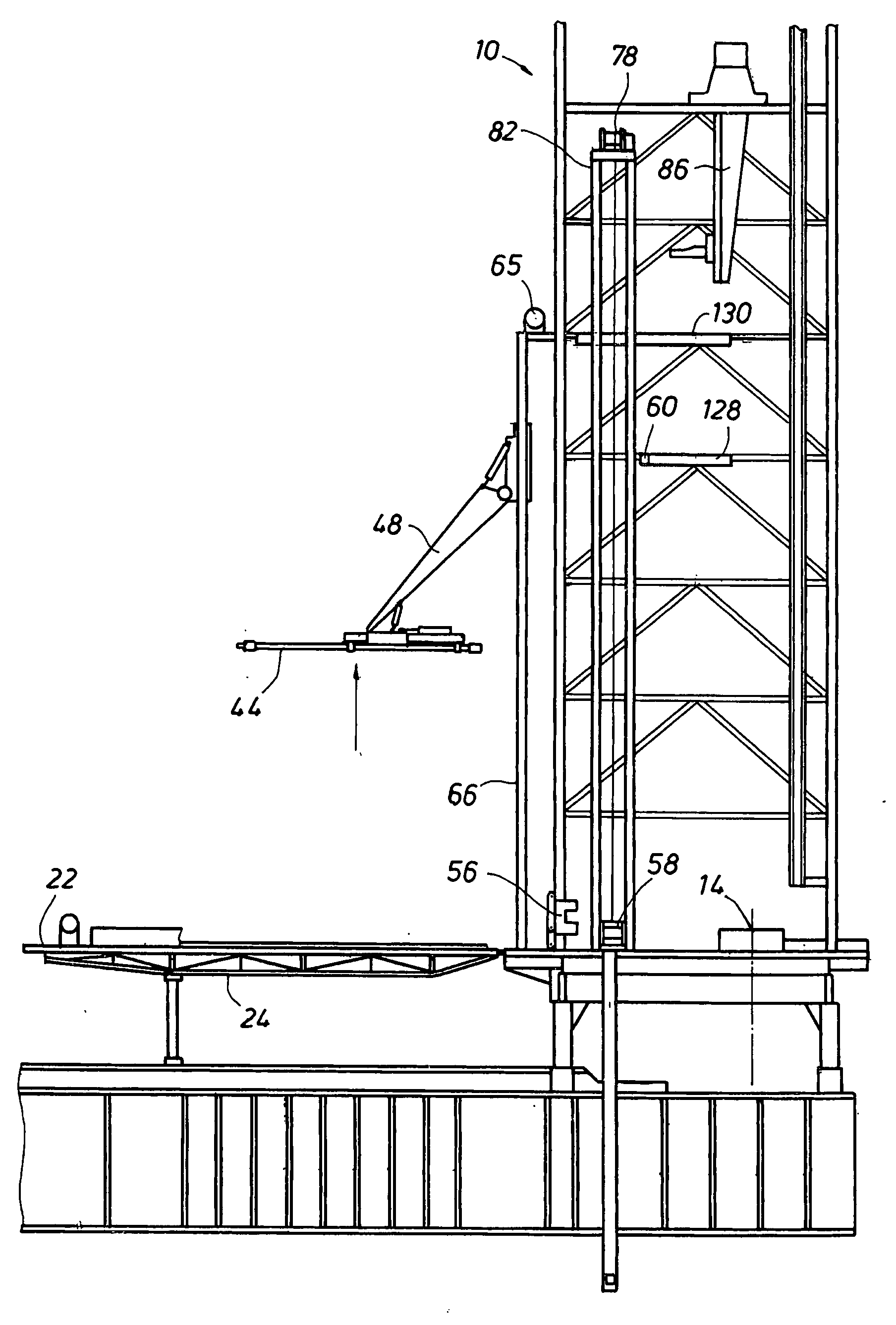
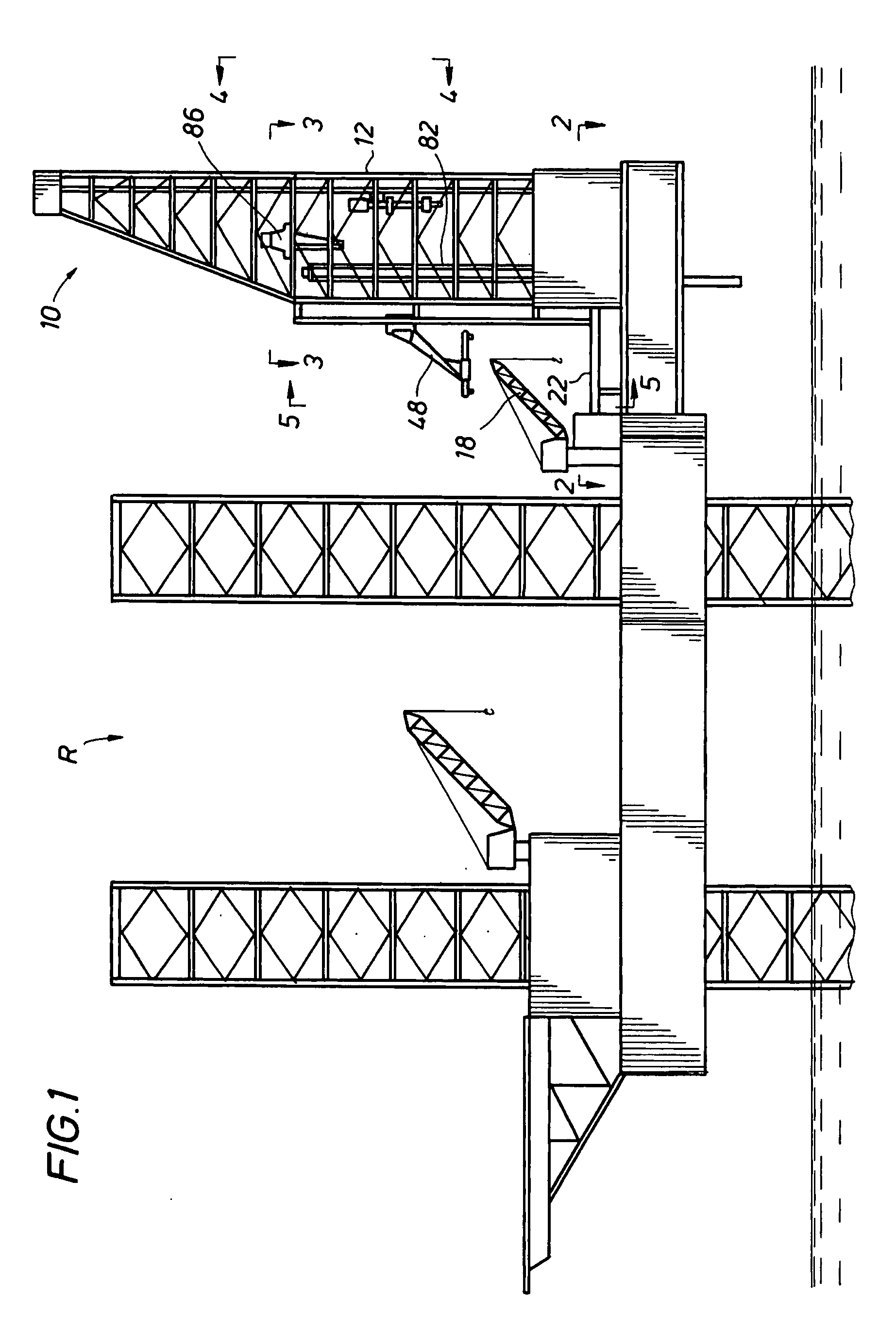
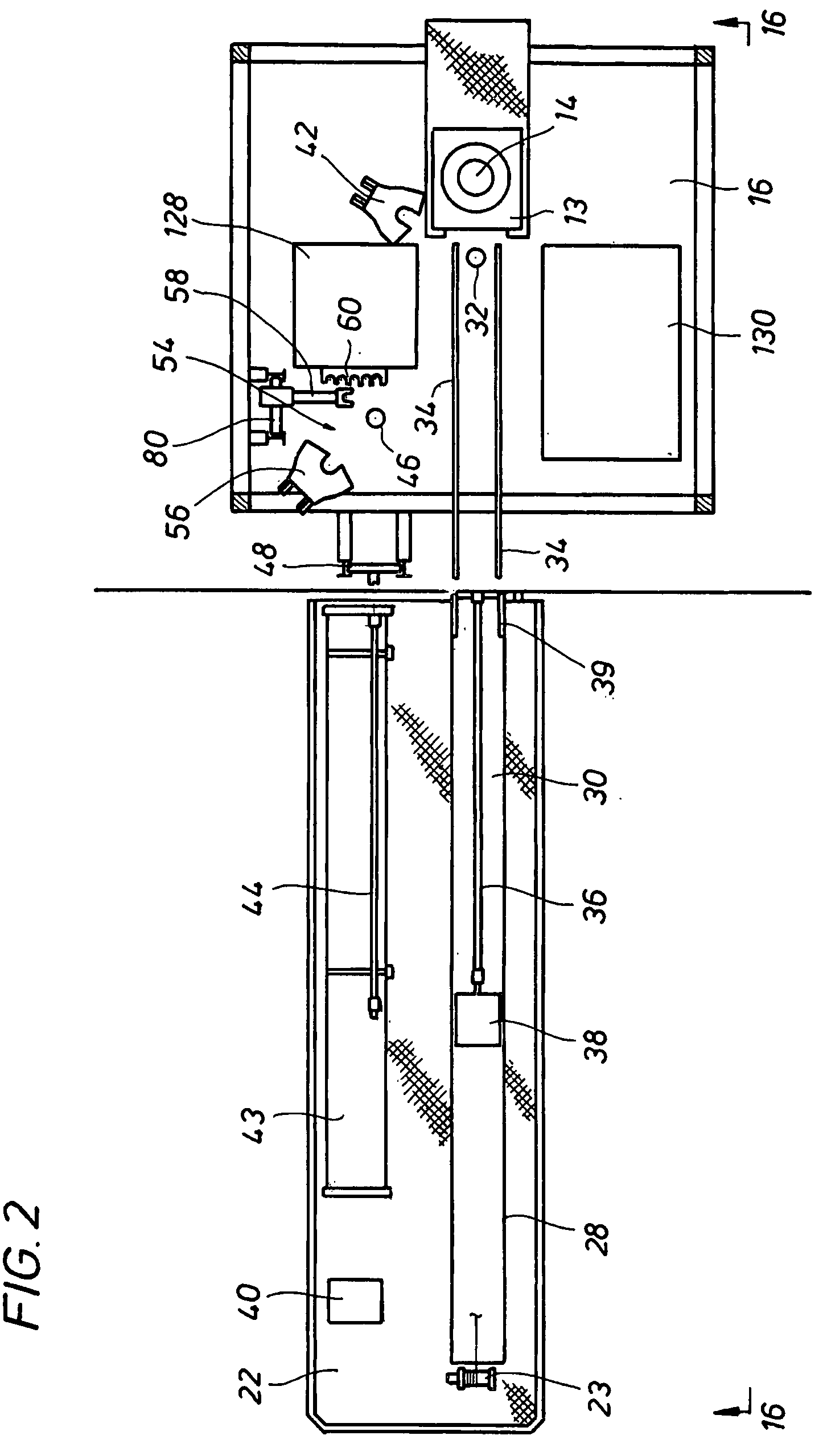
[0052]The present invention involves a system and method for offline building of tubular stands, while drilling operations are simultaneously and independently occurring. As shown in the drawings, this offline stand building comprises moving tubulars from a horizontal position on the catwalk 22 adjacent to the V-door 26 of the derrick 10, lifting and guiding the tubulars in the same plane to a vertical position directly above a preparation hole 46 with a horizontal to vertical arm 48, lowering the vertically positioned tubulars into the preparation hole 46, using a stand arm 58 to move the tubulars in the vertical position for connection into a stand by an auxiliary tubular make up device 56, and transporting the stand vertically to an auxiliary tubular racking station 60 in the upper part of the derrick 10. A bridge racker crane 86 transports the tubular stands from the auxiliary tubular racking station 60 to either the top drive 12, or to first 128 or second 130 tubular racking st...


PUM


Abstract

A system and method for building and handling oilfield tubular stands while drilling operations are simultaneously and independently occurring with one drilling deck, one derrick, and one rotary system. An offline guided path horizontal to vertical arm lifts and moves in the same plane tubulars stored horizontally on the catwalk and positions the tubulars vertically directly into a preparation hole for assembling and disassembling tubular stands while online drilling operations are simultaneously being conducted. A stand arm lifts and lowers the tubulars into and out of the adjustable preparation hole, and transports the tubulars for storage to an auxiliary tubular racking station in the upper part of the derrick. A bridge racker crane moves tubular stands from the auxiliary tubular racking station to the top drive or another tubular racking station.

Description

CROSS-REFERENCE TO RELATED APPLICATIONS[0001]N / ASTATEMENT REGARDING FEDERALLY SPONSORED RESEARCH OR DEVELOPMENT[0002]N / AREFERENCE TO MICROFICHE APPENDIX[0003]N / ABACKGROUND OF THE INVENTION[0004]1. Field of the Invention[0005]This invention relates to a novel method and system for transporting, assembling, storing, and disassembling oilfield tubulars in and around a single drilling deck, derrick, and rotary system while drilling operations are simultaneously and independently occurring.[0006]2. Description of the Related Art[0007]Drilling for oil and gas with a rotary drilling rig is being undertaken to increasingly greater depths both offshore and on land. The increase in depth translates into longer drilling time, and increased cost. The cost to operate such rigs is already substantial (rental rates for some offshore rigs can exceed U.S. $400,000 to $500,000 per day). Therefore, any productive operation that can be accomplished independently of drilling operations to save even smal...

Claims


Application Information

Patent Timeline
Patent Type & Authority Applications(United States)
IPC IPC(8): E21B19/16E21B19/00
CPCE21B19/20E21B19/155
Inventor CHILDERS, MARK ALANLARKIN, BRENDAN WILLIAMRICH, HARVEY MARKSMITH, BARRY M.
Owner FRIEDE & GOLDMAN UNITED BV
Learn More