
Coding method conversion apparatus

a conversion apparatus and coding method technology, applied in the field of coding method conversion apparatuses, can solve the problems of blurred images, inability to determine the filter strength offset of the h.264/avc standard, and the filtering position of the deblocking filter cannot be determined appropriately, so as to prevent blurred images

Inactive Publication Date: 2008-08-21
GK BRIDGE 1
View PDF14 Cites 105 Cited by
  • Summary
  • Abstract
  • Description
  • Claims
  • Application Information

AI Technical Summary

Benefits of technology

[0010]In order to address the above problems, an object of the present invention is to provide a coding method conversion apparatus which can appropriately set filtering positions of a deblocking filter and a filter strength offset, and also prevent blurs in images even if the image is coded by a high coding rate.

Problems solved by technology

Therefore, if the filter strength is adjusted depending only on a coding type of a decoded signal as disclosed in the conventional technology, the filtering positions of the deblocking filter and the filter strength offset of the H.264 / AVC standard cannot be determined appropriately, since the information used for the determination is only the coding type of the decoded signal.
Moreover, the block noise is generally more noticeable when image is coded by a lower coding rate, so that if the filter strength is determined using only the coding type information of the decoded signal not using other information such as rate information, a problem such as noticeable blurs in images occurs when the image is coded by a high coding rate by which an adequate coded amount is allocated to residual data.

Method used


Image

  • Coding method conversion apparatus
  • Coding method conversion apparatus
  • Coding method conversion apparatus

Examples


Embodiment Construction

)

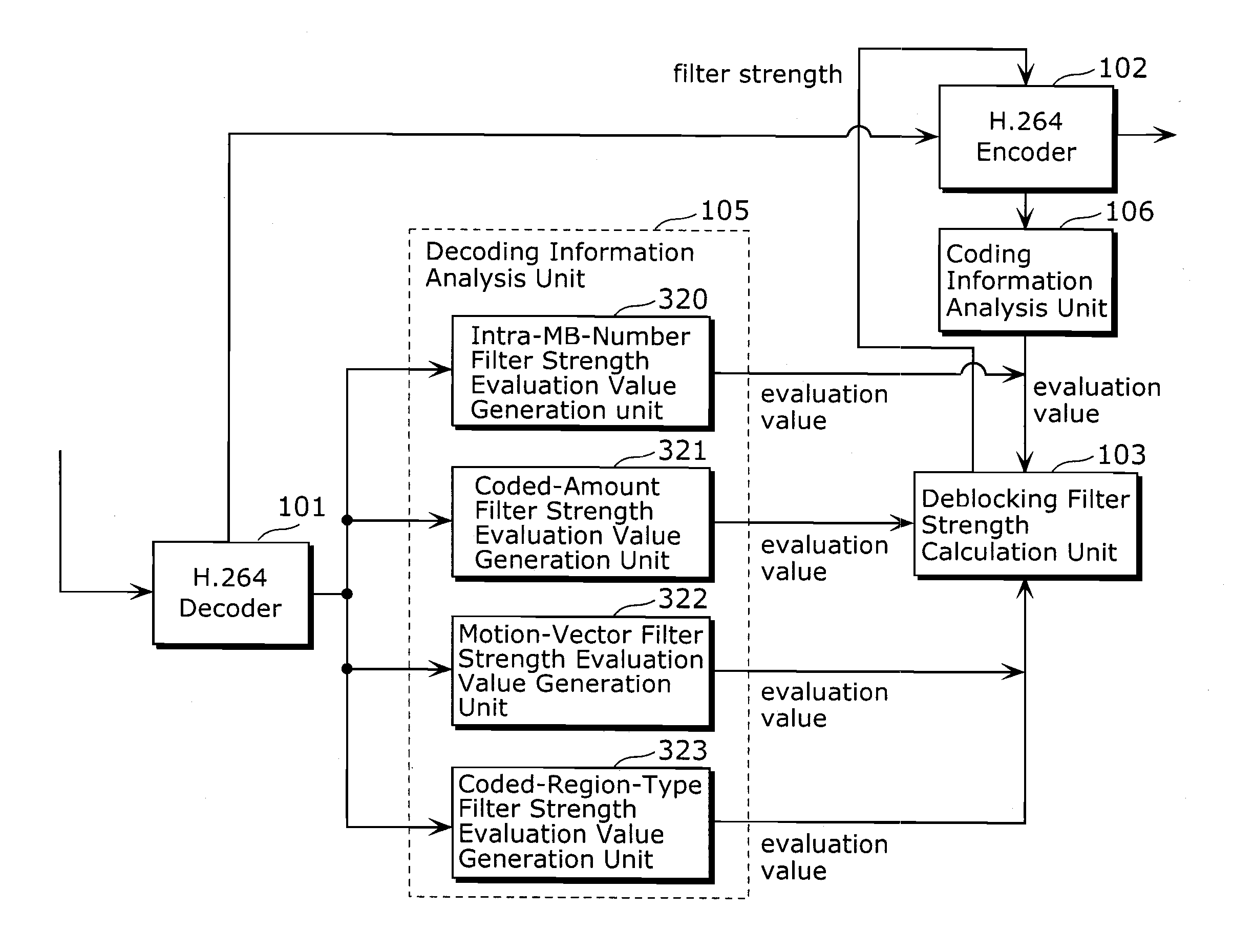
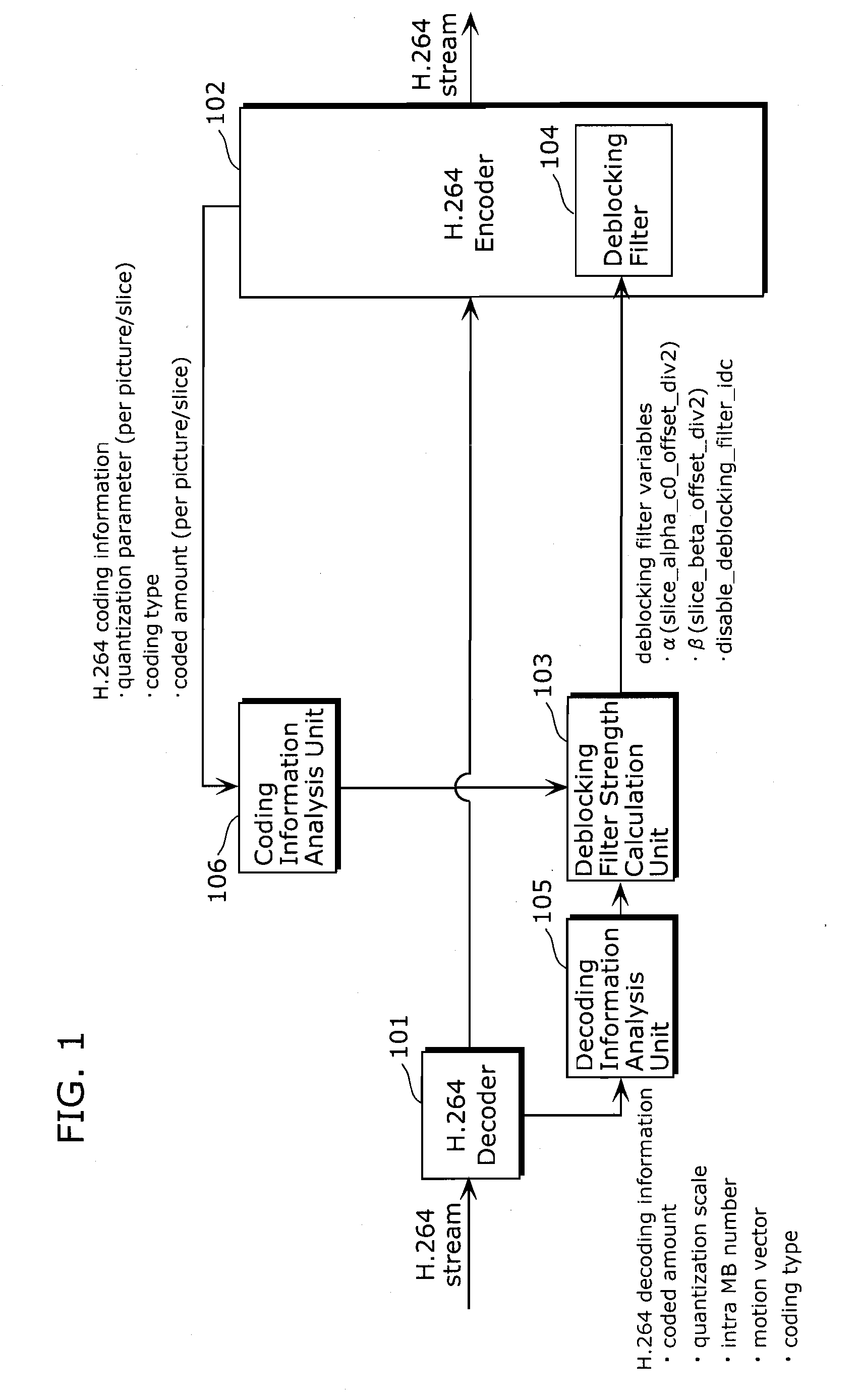
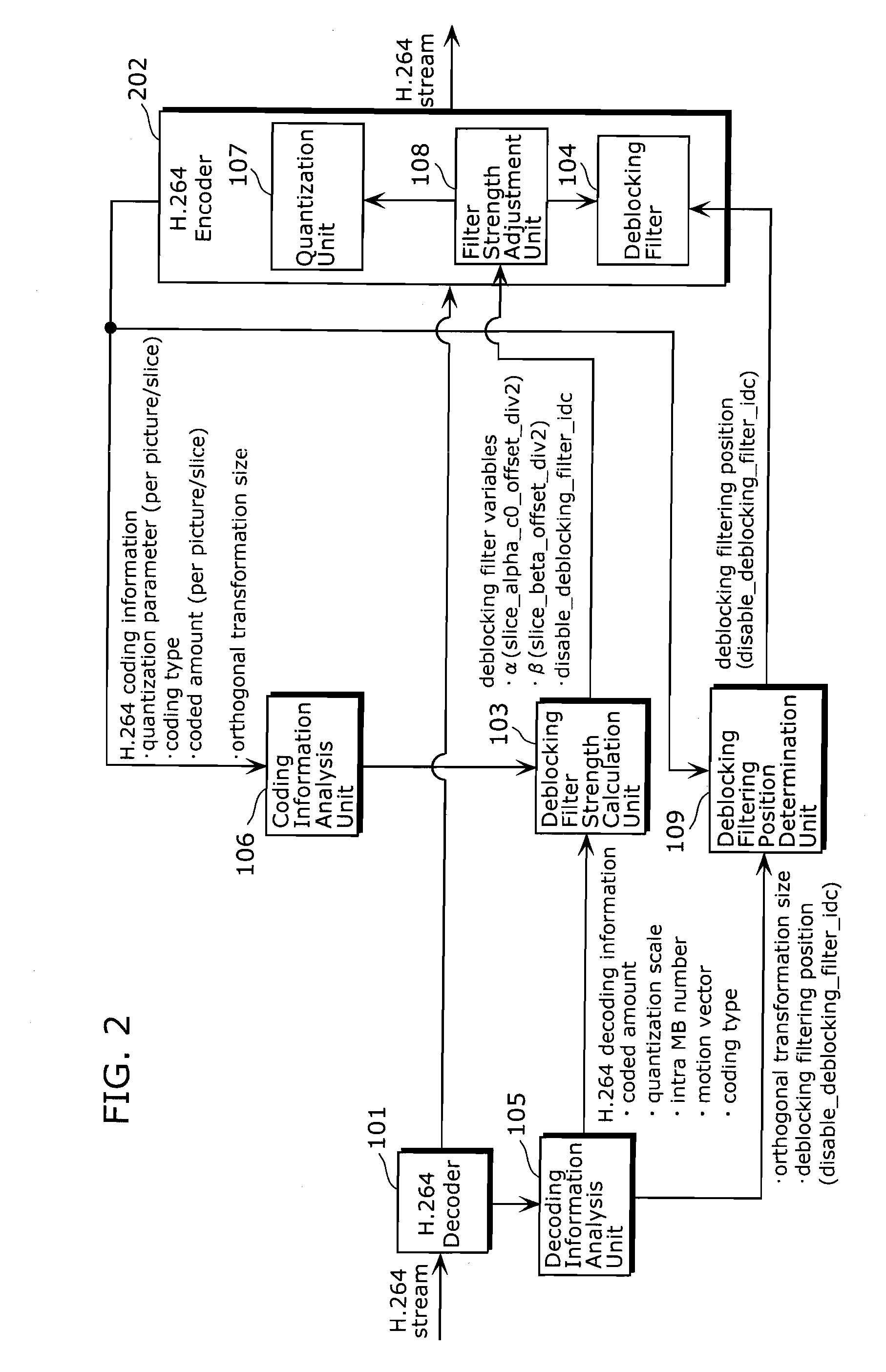
[0023]FIG. 1 is a schematic block diagram showing a structure of a coding method conversion apparatus according to an embodiment of the present invention. The schematic block diagram converts the first image compression coding method into the second image compression coding method, in other words, converts image coded by the first image compression coding method into image coded by the second image compression coding method. Here, the first image compression coding method is assumed to be a low-resolution H.264 / AVC method, and the second image compression coding method is assumed to be a high-resolution H.264 / AVC method The coding method conversion apparatus according to the present embodiment of FIG. 1 determines a strength and filtering positions of a deblocking filter in an encoder, based not only on a coding type of a decoded signal but also on other information. The coding method conversion apparatus of FIG. 1 includes an H.264 decoder 101, an H.264 encoder 102, a deblocking f...


PUM


Abstract

A coding method conversion apparatus converts the first coded data coded by the first coding method into the second coded data. The coding method conversion apparatus includes: an H.264 decoder which decodes the first coded data; a deblocking filter strength calculation unit which calculates a filter strength of deblocking filtering of a second coding method, using at least one piece of decoding information except a coding type of the first coded data, the decoding information being obtained by decoding the first coded data; and a deblocking filter which performs the deblocking filtering to reduce noise in a boundary of blocks according to the filter strength calculated by the deblocking filter strength calculation unit.

Description

BACKGROUND OF THE INVENTION[0001](1). Field of the Invention[0002]The present invention relates to coding method conversion apparatuses which code image information of moving pictures, and more particularly to a coding method conversion apparatus which performs variable length coding on quantized Discrete Cosine Transform (DCT) coefficients and outputs the coded data.[0003](2). Description of the Related Art[0004]For technologies of coding moving pictures, coding efficiency has been improved. This allows mobile telephones to serve as television telephones having smooth moving images, capture high-quality moving pictures, and the like. With the development of coding technologies, conversion between different coding technologies has become necessary to share moving picture data between different apparatuses, to achieve long-length recording, and the like. For example, terrestrial digital television broadcast employs a moving picture coding technology called an MPEG-2 method. When TV p...

Claims


Application Information

Patent Timeline
Patent Type & Authority Applications(United States)
IPC IPC(8): G06K9/36H04N19/117H04N19/134H04N19/50H04N19/136H04N19/139H04N19/146H04N19/157H04N19/167H04N19/176H04N19/196H04N19/40H04N19/60H04N19/86
CPCH04N19/139H04N19/159H04N19/176H04N19/172H04N19/46H04N19/86H04N19/61H04N19/117H04N19/146H04N19/174H04N19/80H04N19/134
Inventor TASAKA, KEIJURI, TATSUROSAIGO, KATSUOOHGOSE, HIDEYUKIARIMURA, KOJIARAKAWA, HIROSHIMARUYAMA, YUKI
Owner GK BRIDGE 1
Learn More