Antenna, earphone antenna, and broadcasting receiver including earphone antenna

Inactive Publication Date: 2008-08-21
SHARP KK
View PDF3 Cites 9 Cited by
  • Summary
  • Abstract
  • Description
  • Claims
  • Application Information

AI Technical Summary

Benefits of technology

[0024]That is, in cases where the antenna of the present invention transmits and receives a radio wave falling within the first frequency range, the second antenna element and the unbalanced power feeder operate as a sleeve antenna. This makes it possible to efficiently transmit and receive a radio wave falling within the first frequency range.
[0063]Further, a broadcasting receiver including such an earphone antenna as described above can receive broadcast waves in a wide frequency range with high sensitivity.

Problems solved by technology

Therefore, the second antenna element connected to the second output port and the unbalanced power feeder line are fed with unbalanced power.
As a result, the second antenna element and the unbalanced power feeder operate as a sleeve antenna.

Method used


Image

  • Antenna, earphone antenna, and broadcasting receiver including earphone antenna
  • Antenna, earphone antenna, and broadcasting receiver including earphone antenna
  • Antenna, earphone antenna, and broadcasting receiver including earphone antenna

Examples


embodiment 1

[0084]An embodiment of the present invention will be described below with reference to FIGS. 1 through 6.

[0085](Outline of an Antenna)

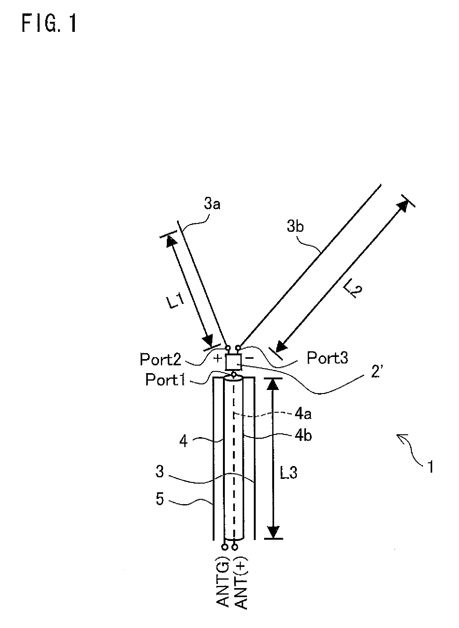
[0086]FIG. 1 is a diagram schematically showing an antenna 1 of the present embodiment. As showing in FIG. 1, the antenna 1 includes an unbalanced / balanced converter 2, an antenna element (first antenna element) 3a, an antenna element (second antenna element) 3b, and a coaxial cable (unbalanced power feeder line) 4. The antenna 1 is arranged such that the antenna element 3a, the antenna element 3b, and the coaxial cable 4 are connected to the unbalanced / balanced converter 2.

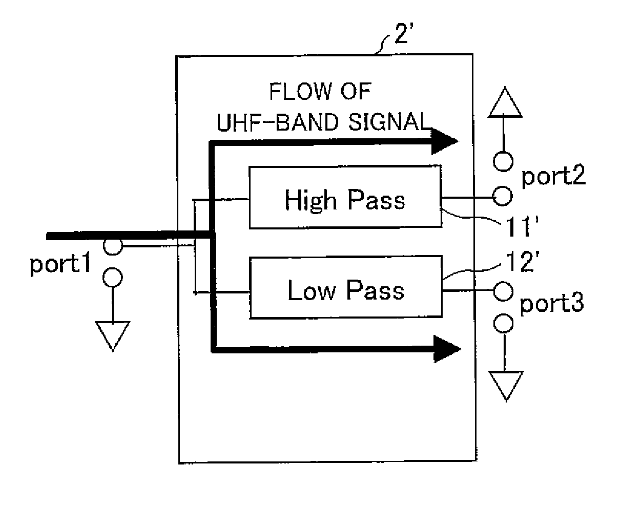
[0087]The unbalanced / balanced converter 2 includes an input terminal port1 (input port) via which to receive an input unbalanced current and a plurality of output terminals port2 and port3 (first output port, second output port) via which to respectively output electrical currents balanced with each other.

[0088]That is, when the input terminal port1 of the unbalanced / balanced conve...

embodiment 2

[0176]In the present embodiment, an example in which the antenna 1 is applied to an earphone antenna will be described with reference to FIGS. 7 through 10. An earphone antenna 21 of the present invention can be suitably used in such a case that FM, VHF, and UHF radio waves are received with use of a mobile terminal. First, an example arrangement in which the antenna 1 of the present invention is combined with a tripolar earphone will be described with reference to FIG. 7. Components having the same functions as those described in the foregoing embodiment are given the same reference numerals, and will not be described below.

[0177](Arrangement of a Conventional Earphone Antenna)

[0178]First, for comparison with the present invention, a conventional earphone antenna will be described with reference to FIG. 14. FIG. 14 is a diagram schematically showing an arrangement of a conventional earphone antenna 101. As shown in FIG. 14, the earphone antenna 101 includes a feeder cable 102, an e...

modified example 1

OF THE EARPHONE ANTENNA

[0238]The following describes a modified example of the earphone antenna 21 with reference to FIG. 8. FIG. 8 is a diagram schematically showing an arrangement of an earphone antenna 31.

[0239]The earphone antenna 31 differs from the earphone antenna 21 of FIG. 7 in that the second audio cables 27LN and 27LP have respective ends, facing the unbalanced / balanced converter 2′, which are connected to each other via a capacitor (first capacitor) 29c, and that the second audio cables 27RN and 27RP have respective ends, facing the unbalanced / balanced converter 2′, which are connected to each other via a capacitor (second capacitor) 29d.

[0240]The provision of the capacitors 29c and 29d allows the earphone antenna 31 to have higher reception sensitivity than the earphone antenna 21 of FIG. 7.

[0241]In cases where the earphone antenna 31 is used to receive a high-frequency signal falling within the VHF band, the high-frequency signal is transmitted to the output terminal ...


PUM


Abstract

An antenna of the present invention includes a coaxial cable, antenna elements (3a and 3b), and an unbalanced / balanced converter. The unbalanced / balanced converter has a high-pass circuit provided between an input terminal port1 and an output terminal port2 and a low-pass circuit provided between the input terminal port1 and an output terminal port3. Moreover, the high-pass circuit rejects frequencies within a VHF band, and the high-pass circuit and the low-pass circuit both pass frequencies within a UHF band. In response to a signal, inputted to the input terminal port1, which falls within the UHF band, the high-pass circuit and the low-pass circuit output signals that are inverted in phase and equal in amplitude with respect to each other. Therefore, the antenna has high transmission and reception sensitivity in a wide frequency range, i.e., in the VHF and UHF bands. This makes it possible to provide an antenna having high transmission and reception sensitivity in a wide frequency range.

Description

[0001]This Nonprovisional application claims priority under 35 U.S.C. § 119(a) on Patent Application No. 032748 / 2007 filed in Japan on Feb. 13, 2007, the entire contents of which are hereby incorporated by reference.FIELD OF THE INVENTION[0002]The present invention relates to antennas that transmit and receive radio waves. An antenna of the present invention exhibits good sensitivity in transmitting and receiving radio waves falling within a wide frequency range, and therefore can be widely applied as an antenna for use in transmission and reception of broadcast waves and the like. Further, the use of the antenna of the present invention, for example, as an earphone antenna makes it possible to enable a mobile television receiver or the like to receive broadcast waves with high sensitivity.BACKGROUND OF THE INVENTION[0003]The conventional analog television broadcasting uses a VHF band (88 MHz to 222 MHz). The ongoing transition from analog to digital broadcasting will cause a big ch...

Claims


Application Information

Patent Timeline
IPC IPC(8): H01Q1/50H01P1/20H03H5/00H01Q1/44H01Q1/46H01Q5/10H01Q5/371H01Q5/50H01Q9/16H01Q21/30H04B1/08H04R1/10
CPCH01Q1/273H01Q9/16H01Q9/30H01Q5/48H01Q5/335H01Q5/40H01Q21/30
Inventor YAMAGUCHI, MOTOFUMISUEMATSU, EIJISUZUKI, HARUO
Owner SHARP KK
Why Eureka
Try Eureka