
Structure mannequin model foot

a technology of structure and model foot, applied in the field of improved structure mannequin model foot, can solve the problem of limited heel height to only one style and size of footwear

Inactive Publication Date: 2008-08-21
G & FAR
View PDF9 Cites 6 Cited by
  • Summary
  • Abstract
  • Description
  • Claims
  • Application Information

AI Technical Summary

Benefits of technology

The present invention is an improved mannequin model that solves the shortcomings of prior art models. It utilizes a detachable design that allows for the separation of the calf and foot piece of the mannequin model. This allows for the assembly of different height and size heel foot pieces to the calves of one single mannequin, making it easy to wear different shoes on different foot pieces. The invention also includes a height-adjustable support anchoring frame that improves upon prior models by securing the entire mannequin model. Overall, the invention provides a more versatile and efficient tool for the display and sale of different footwear.

Problems solved by technology

Even though this is the case, since the prior art mannequin model support points are on both feet, which thereby keeps the mannequin model stationary, and because the support and vertical bracing means is totally reliant on placement against both feet, the two feet of the prior art mannequin model are permanently disposed and thus cannot be replaced or disassembled; as a result, since said mannequin model serves primarily as a means of displaying apparel and although capable of wearing a pair of shoes, the heel height is limited to only one style and size of footwear.

Method used


Image

  • Structure mannequin model foot
  • Structure mannequin model foot
  • Structure mannequin model foot

Examples


Embodiment Construction

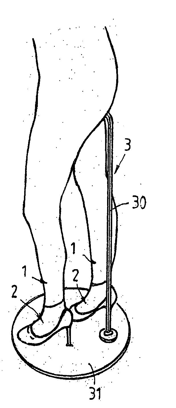
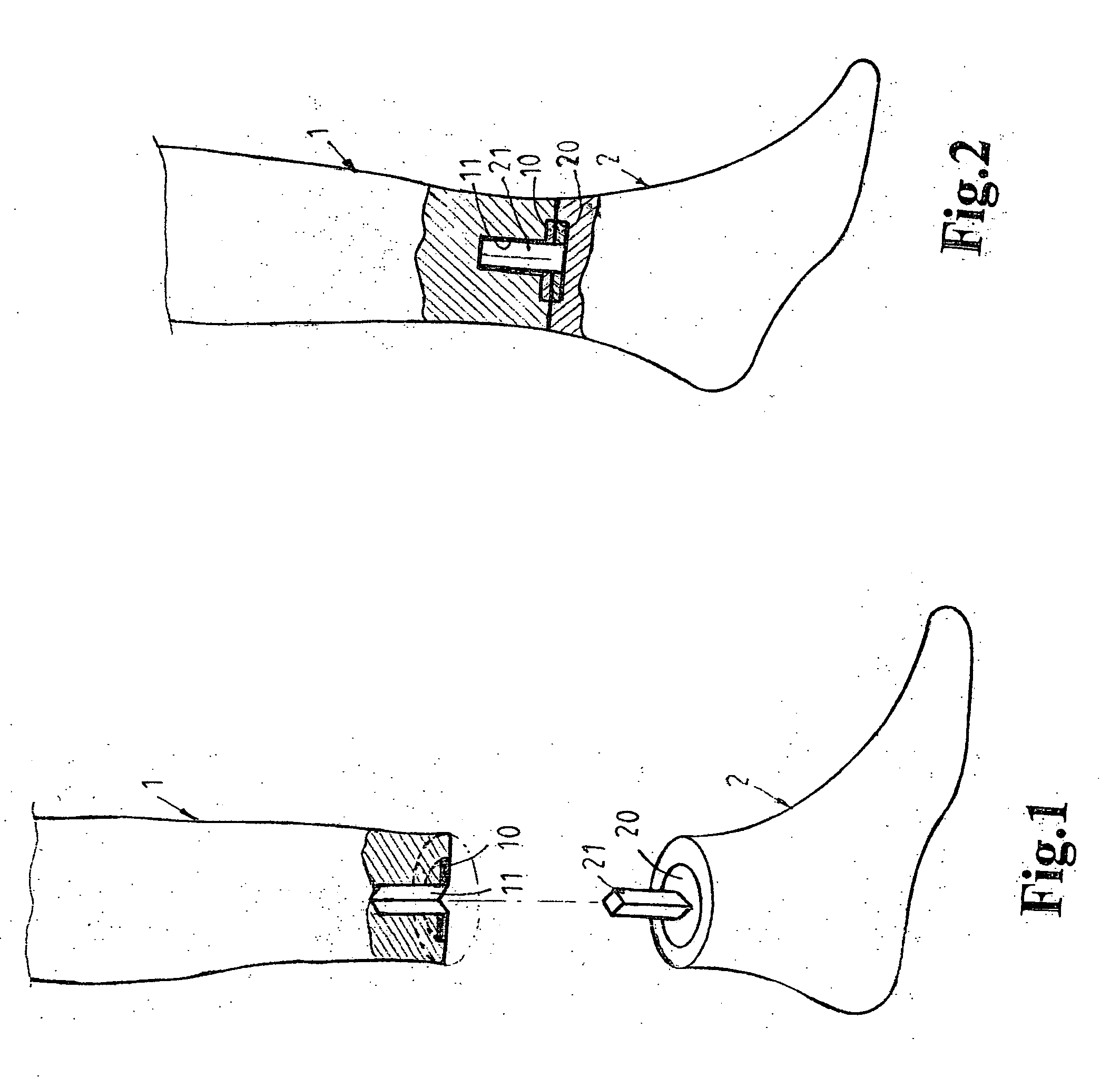
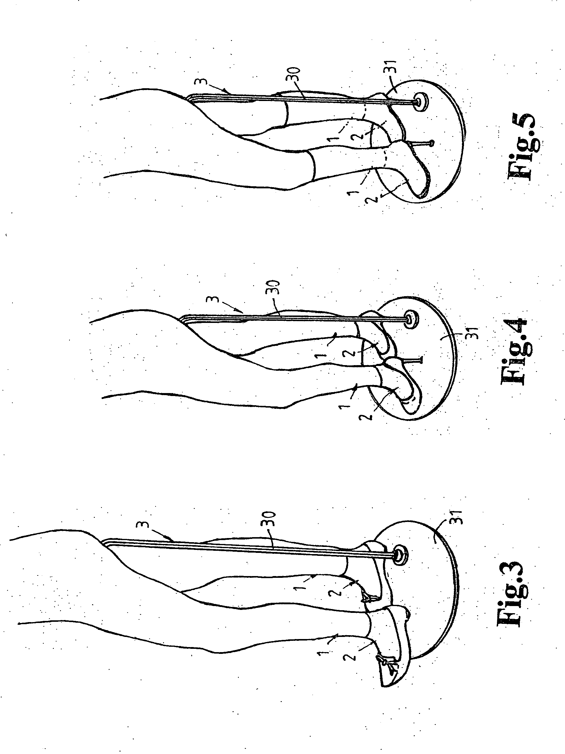
[0017]Referring to FIG. 1 and FIG. 2, the invention herein is comprised of a mannequin model calf 1 and a foot piece 2 designed to be separable into two physical entities, wherein a magnet 10 and a polygonal guide hole or a polygonal stud 11 is disposed in the crosscut surface of the calf 1, and a magnet 20 and a polygonal stud or a polygonal guide hole 21 is disposed in the facing crosscut surface of the foot piece 2, the interfitting of the polygonal guide hole or the polygonal stud 11 with the polygonal stud or the polygonal guide hole 21 as well as the mutual attraction between the magnets 10 and 20 enabling the foot piece 2 to be easily assembled onto the mannequin model calf 1 without coming apart and, furthermore, since the guide hole 11 and the stud 21 are designed as polygonal in shape, the foot piece 2 cannot rotate on the mannequin model calf 1, the interlocking assembly relationship between said foot piece 2 and the mannequin model calf 1 is staggered such that in the ev...


PUM


Abstract

An improved structure mannequin model foot comprised of a mannequin model calf and a foot piece designed to be separable into two physical entities, the foot piece and calf detachment capability enabling the assembling of different height and size heeled foot pieces to the calves of one single mannequin, thereby facilitating the wearing of different shoes on different foot pieces, to achieve, on the same single mannequin model, the objective of alternating the assembly of different foot pieces to display assorted footwear (such as low, medium, and high heel shoes as well as riding boots, etc.).

Description

BACKGROUND OF THE INVENTION[0001]1) Field of the Invention[0002]The invention herein relates to a improved structure mannequin model foot, specifically a mannequin model foot structure in which the foot piece is easily changed to facilitate the wearing of different shoes.[0003]2) Description of the Prior Art[0004]Mannequin models are utilized for the displaying of apparel and footwear that are worn on them, which not only enables the exhibiting of apparel and footwear in a stationary, fully revealing presentation, but also provides for greater durability and economic advantage than live models because they are “motionless articles” capable of long-term placement in shops for the merchandising of apparel and footwear. Even though this is the case, since the prior art mannequin model support points are on both feet, which thereby keeps the mannequin model stationary, and because the support and vertical bracing means is totally reliant on placement against both feet, the two feet of t...

Claims


Application Information

Patent Timeline
Patent Type & Authority Applications(United States)
IPC IPC(8): D06C15/00
CPCA47F8/00G09B23/30G09B23/34
Inventor TU, YUEH-MEI
Owner G & FAR
Learn More