
Temperature sensor

a technology of temperature sensor and sensor, which is applied in the direction of semiconductor/solid-state device testing/measurement, pulse technique, instruments, etc., can solve the problem that the conventional temperature sensor consumes a lot of time to test products

Active Publication Date: 2008-08-14
SK HYNIX INC
View PDF29 Cites 19 Cited by
  • Summary
  • Abstract
  • Description
  • Claims
  • Application Information

AI Technical Summary

Benefits of technology

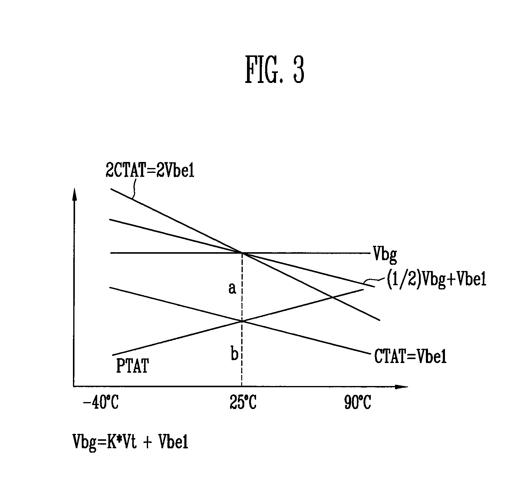
The present invention is about a temperature sensor that uses a special circuit to generate a reference voltage. This reference voltage remains constant regardless of changes in external temperature. The sensor compares this reference voltage to the actual temperature, and outputs a signal to indicate the range of temperatures that are present. This allows for accurate temperature sensing even in situations where the external temperature is not very hot or very cold.

Problems solved by technology

However, the conventional temperature sensor consumes much time to test products due to the time required to cut the fuse.

Method used


Image

  • Temperature sensor
  • Temperature sensor
  • Temperature sensor

Examples


Embodiment Construction

[0015]Specific embodiments according to the present invention will be described with reference to the accompanying drawings.

[0016]FIG. 1 is a block diagram showing a construction of a temperature sensor according to an embodiment of the present invention.

[0017]The temperature sensor 100 includes a compare subject voltage output unit 110 for outputting a to-be-compared voltage that becomes a basis for determining a range of an external temperature, a temperature range decision unit 120 for outputting an enable signal that identifies whether the external temperature is different from normal temperature based on the to-be-compared voltage, and a temperature signal output unit 130 for outputting a specific one of a plurality of high temperature signals or a specific one of a plurality of low temperature signals, which indicates the range of the external temperature, in response to the enable signal.

[0018]FIG. 2 is a circuit diagram of the compare subject voltage output unit 110 accordin...


PUM

PropertyMeasurementUnit
temperatureaaaaaaaaaa
temperature voltageaaaaaaaaaa

Abstract

A temperature sensor includes a compare subject voltage output unit, a temperature range decision unit, and a temperature signal output unit. The compare subject voltage output unit is configured to output a reference voltage having a constant value irrespective of a change of an external temperature and a third temperature voltage that decreases in response to an increase of an external temperature. The temperature range decision unit is configured to compare the reference voltage and the third temperature voltage, and output an enable signal, to indicate whether the external temperature is different from a normal temperature. The temperature signal output unit is configured to output a specific one of a plurality of high temperature signals or a specific one of a plurality of low temperature signals, to indicate a range of the external temperature, in response to the enable signal.

Description

CROSS-REFERENCES TO RELATED APPLICATIONS[0001]The present application claims priority to Korean patent application number 10-2007-15351, filed on Feb. 14, 2007, which is incorporated by reference in its entirety.BACKGROUND OF THE INVENTION[0002]The present invention relates to a semiconductor temperature sensor and, more particularly, to a temperature sensor, which is configured to sense an external temperature and output the range of a sensed temperature as an electrical signal by employing a band gap reference voltage generating circuit that provides a constant level of a reference voltage irrespective of a temperature change.[0003]In the prior art, a temperature sensor that employs a method of directly sensing a temperature in a low temperature environment, a high temperature environment, etc. and cutting a fuse is well known. However, the conventional temperature sensor consumes much time to test products due to the time required to cut the fuse.BRIEF SUMMARY OF THE INVENTION[00...

Claims


Application Information

Patent Timeline
Patent Type & Authority Applications(United States)
IPC IPC(8): G01K7/01G05F3/16
CPCG01K7/015G01K3/00H01L22/00
Inventor RYU, JE IL
Owner SK HYNIX INC
Learn More