
High thermal conductivity packaging for solid state light emitting apparatus and associated assembling methods

a technology of solid-state light emitting apparatus and packaging method, which is applied in the direction of signalling/lighting device, discharge tube/lamp details, lighting support device, etc., can solve the problems of degrading device performance and/or reliability, and the technique may not be as effective in at least partially enclosed housing, so as to achieve the effect of higher thermal conductivity

Active Publication Date: 2008-08-14
IDEAL IND LIGHTING LLC
View PDF98 Cites 70 Cited by
  • Summary
  • Abstract
  • Description
  • Claims
  • Application Information

AI Technical Summary

Benefits of technology

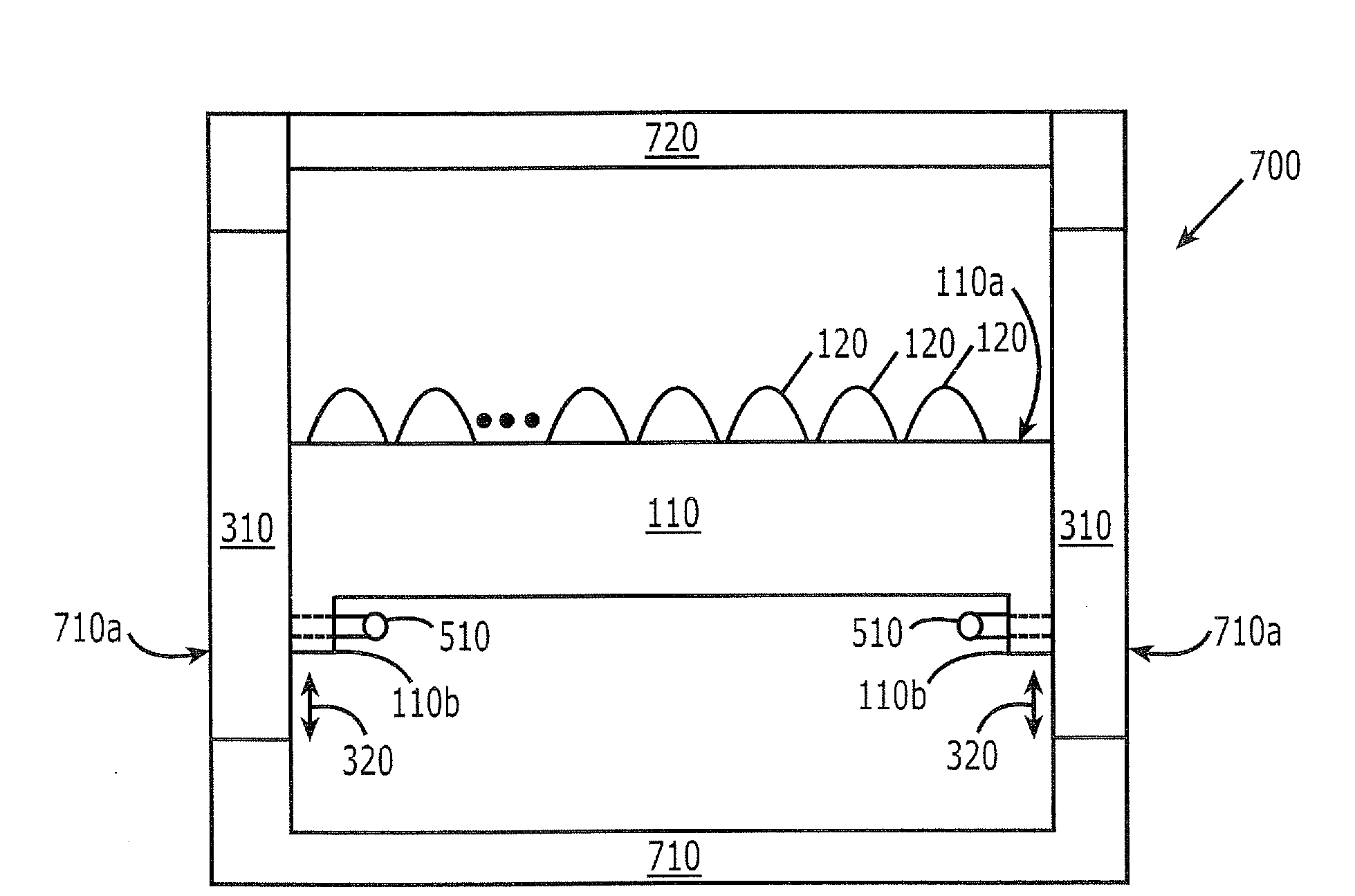
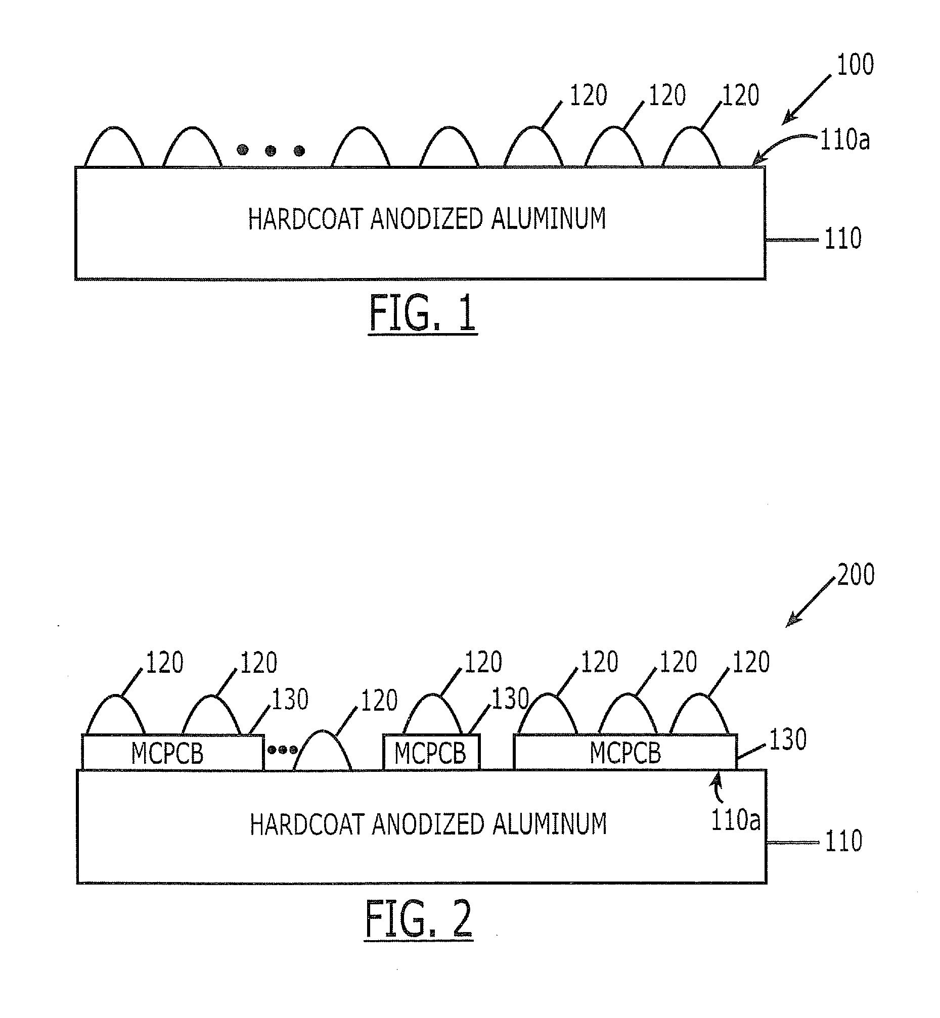
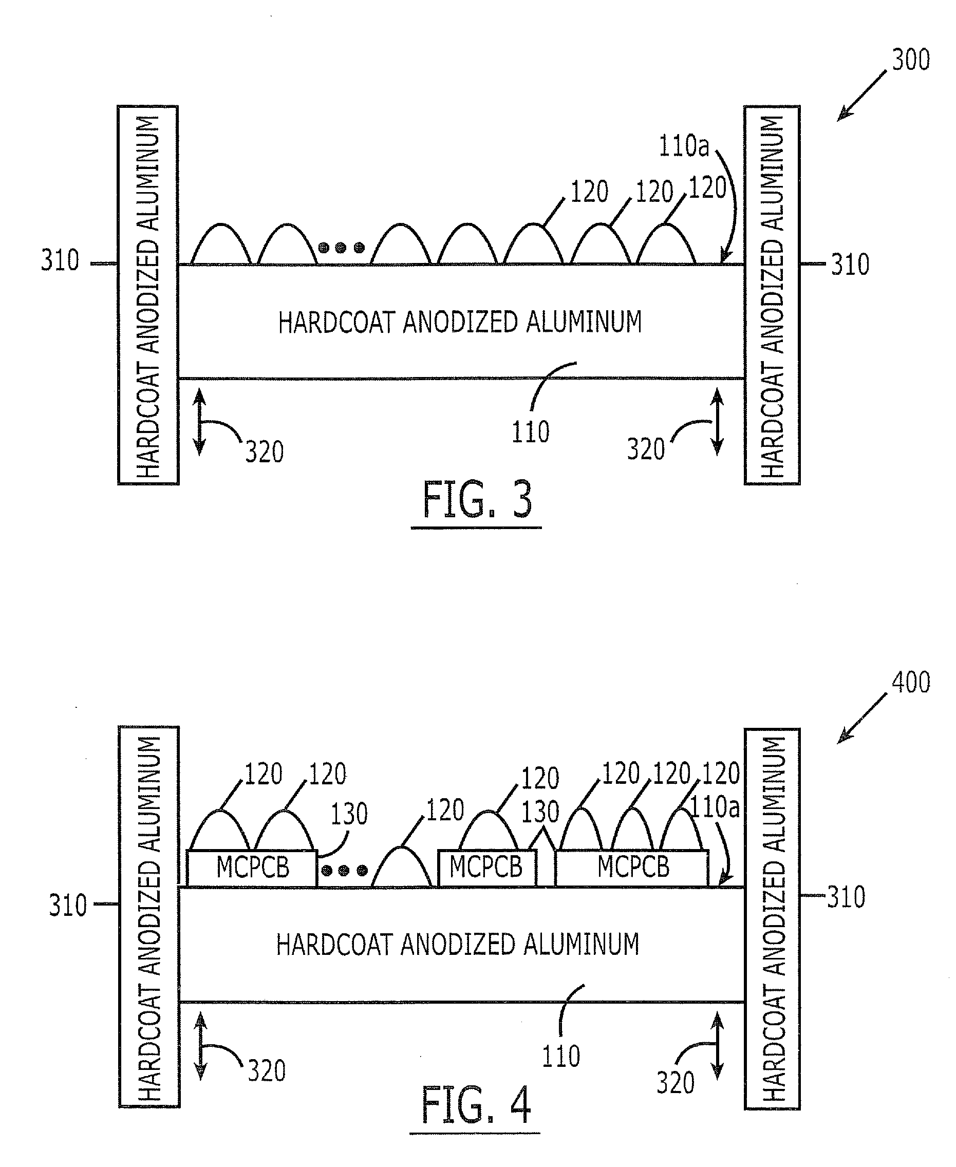
The present invention provides a light emitting apparatus that includes a hardcoat anodized aluminum substrate and a plurality of solid state light emitting elements mounted on the substrate. The substrate can be a planar or disk-shaped substrate. The apparatus also includes a housing that holds the substrate and includes elongated apertures and heat conducting bars to dissipate heat from the solid state light emitting elements. The substrate can be slidably mounted in the housing and the position of the substrate can be adjusted and fixed. The technical effects of the invention include improved heat dissipation and a compact size of the light emitting apparatus.

Problems solved by technology

Although solid state light emitting elements, such as LEDs, may be more efficient that conventional incandescent light bulbs, the LEDs may still generate substantial heat under operating conditions, which may degrade device performance and / or reliability.
However, these techniques may not be as effective when used in at least partially enclosed housings.

Method used


Image

  • High thermal conductivity packaging for solid state light emitting apparatus and associated assembling methods
  • High thermal conductivity packaging for solid state light emitting apparatus and associated assembling methods
  • High thermal conductivity packaging for solid state light emitting apparatus and associated assembling methods

Examples


example

[0044]The following Example shall be regarded as merely illustrative and shall not be construed as limiting the invention.

[0045]In order to measure the thermal efficiency between hard anodized aluminum substrates and unpolished aluminum substrates, two fixtures were created with ten blue XLamp 7090 XR-E series LEDs mounted on 1″×12″ strips. The strips are distributed by McMaster-Carr Supply Company (mcmaster.com). Part No. 6023K151 is a hardcoat anodized aluminum strip and Part No. 9134K111 is an unpolished, unanodized aluminum strip. These aluminum strips are also available from many other sources. Table 1 illustrates the temperature differentials between the LED housing and the back of the strip over time for the hardcoat anodized aluminum substrate, and Table 2 shows these temperature differentials for the unpolished aluminum sheet.

TABLE 1Hardcoat 6023K151Time (minutes)LED housingBack of stripDifference:0021.5° C.21.5° C.0.0° C.:0540.3° C.40.0° C.0.3° C.:1041.3° C.41.4° C.0.1° C....


PUM

PropertyMeasurementUnit
transparentaaaaaaaaaa
thermal conductivityaaaaaaaaaa
heataaaaaaaaaa

Abstract

One or more solid state light emitting elements are mounted on a hardcoat anodized aluminum substrate. One or more bars also may be provided that slidably contact an edge of the hardcoat anodized aluminum substrate. The substrate and the bar(s) may be mounted in a housing with the bars mounted in apertures in the housing wall. Related assembling methods for solid state light emitting apparatus also are disclosed.

Description

FIELD OF THE INVENTION[0001]This invention relates to solid state light emitting apparatus, and more particularly to packaging techniques and methods for solid state light emitting apparatus.BACKGROUND OF THE INVENTION[0002]Solid state light emitting apparatus are being widely designed and marketed as replacements for conventional incandescent lighting apparatus and / or other conventional lighting applications. Solid state light emitting apparatus can include solid state flashlights, spotlights, searchlights, headlights, pixels for arena displays, recessed lighting, light fixtures and / or other solid state lighting devices. Such solid state light emitting apparatus generally include a mounting substrate and a plurality of solid state light emitting elements, such as Light Emitting Diodes (LEDs), on the mounting substrate. A housing is configured for mounting the substrate therein. Optical elements, such as lenses, solid state light emitting element drivers and / or other support circuit...

Claims


Application Information

Patent Timeline
Patent Type & Authority Applications(United States)
IPC IPC(8): F21V29/00B23P11/00F21V15/01
CPCF21V19/02F21V29/004F21Y2101/02Y10T29/49826H05K2201/10106H05K2203/0315H05K1/053F21V29/70F21Y2115/10
Inventor VILLARD, RUSSELL GEORGE
Owner IDEAL IND LIGHTING LLC
Learn More