Angle-adjustable display holder

Inactive Publication Date: 2008-08-14
LIANG JHIH JHANG
View PDF10 Cites 5 Cited by
  • Summary
  • Abstract
  • Description
  • Claims
  • Application Information

AI Technical Summary

Benefits of technology

[0005]Although many manufacturers have spent a lot of time to improve the above-mentioned drawback, no effective method has been provided to overcome this drawback. In view of this, the present inventor has s

Problems solved by technology

Although many manufacturers have spent a lot of time to improve the above-mentioned drawback, no effective method has been provided to overcome this drawback.

Method used


Image

  • Angle-adjustable display holder
  • Angle-adjustable display holder
  • Angle-adjustable display holder

Examples


Embodiment Construction

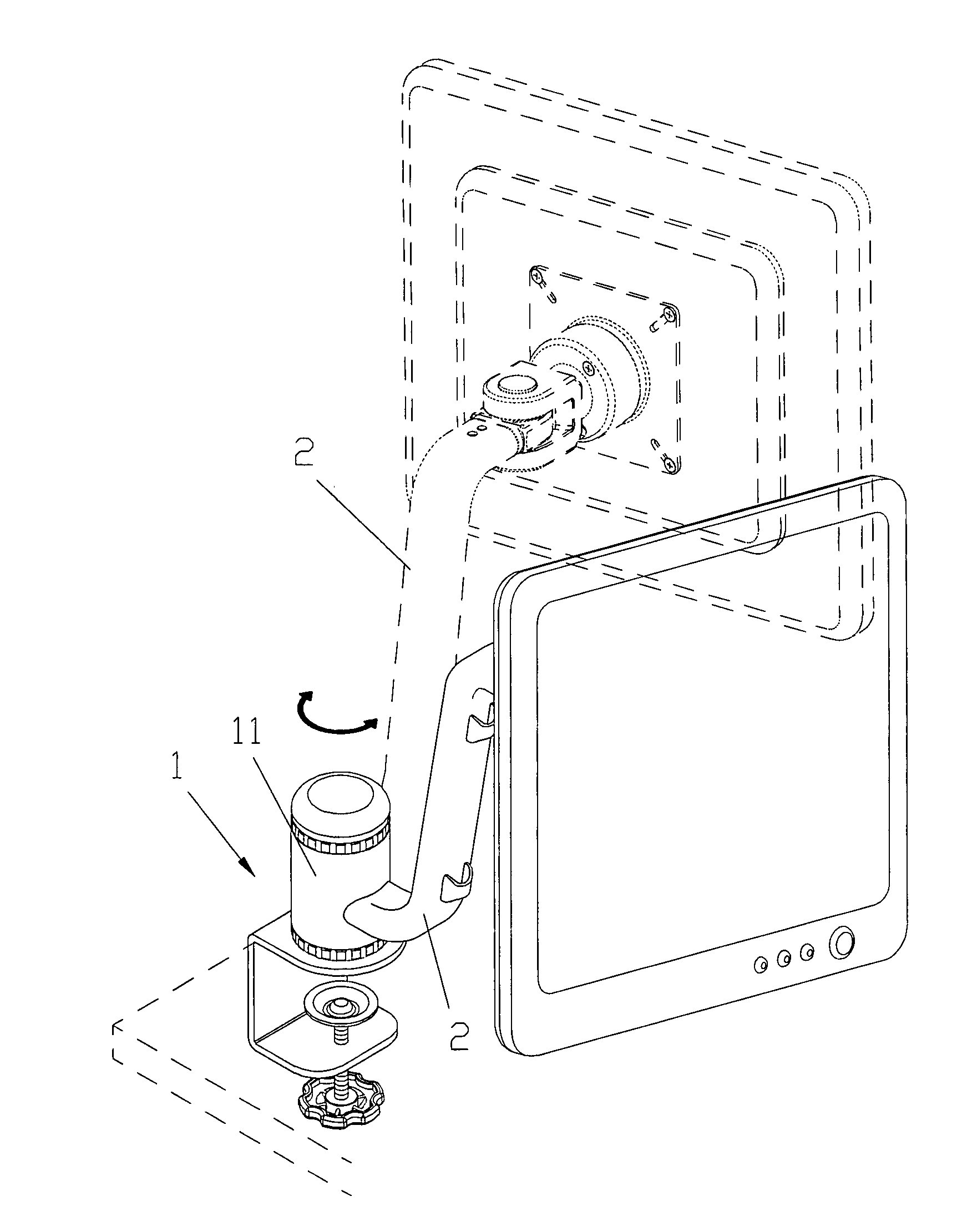
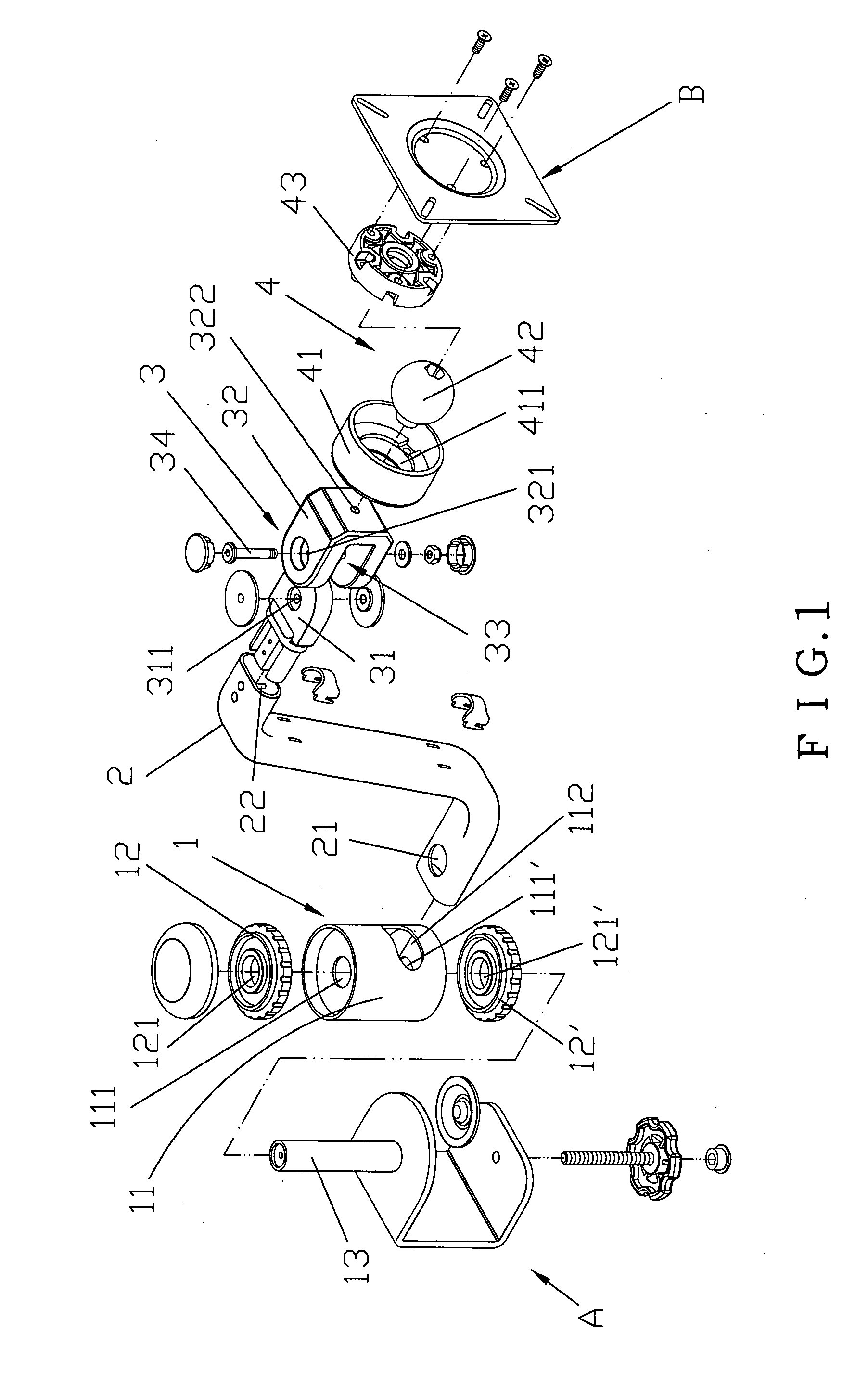
[0016]FIG. 1 is a pictorially exploded view showing an angle-adjustable display holder according to the invention. As shown in FIG. 1, the display holder is mainly composed of a first adjusting mechanism 1, a frame 2, a second adjusting mechanism 3 and a third adjusting mechanism 4. The first adjusting mechanism 1 is composed of a rotatable head 11, two fitting covers 12, 12′ and one shaft rod 13. The rotatable head 11 has upper and lower ends respectively formed with shaft holes 111, 111′, and a lateral side formed with an accommodating slot 112. Central portions of the fitting covers 12, 12′ are also formed with shaft holes 121, 121′. The shaft rod 13 is fixed on a mounting seat A. One end of the frame 2 is formed with a shaft hole 21, and the other end of the frame 2 is formed with an accommodating slot 22. The second adjusting mechanism 3 is composed of a shaft block 31 and a pivoting block 32. The shaft block 31 is formed with a shaft hole 311, and the pivoting block 32 is form...


PUM


Abstract

The invention provides an angle-adjustable display holder, and more particularly a position-adjustable and angle-adjustable display holder, which is mainly composed of a first adjusting mechanism, a frame, a second adjusting mechanism and a third adjusting mechanism. Moving the first adjusting mechanism may move the display holder leftwards or rightwards. Moving the second adjusting mechanism may move a display held by the holder leftwards or rightwards. Moving the third adjusting mechanism can adjust an angle of the display.

Description

BACKGROUND OF THE INVENTION[0001](1) Field of the Invention[0002]The invention relates to an angle-adjustable display holder composed of a first adjusting mechanism, a frame, a second adjusting mechanism and a third adjusting mechanism. Moving the first adjusting mechanism may move the display holder leftwards or rightwards. Moving the second adjusting mechanism may move a display held by the holder leftwards or rightwards. Moving the third adjusting mechanism can adjust an angle of the display.[0003](2) Description of the Prior Art[0004]Displays may be applied to various applications, such as a television, a computer, a vehicle, a VCD or a DVD. However, most of the displays in various occasions are fixed, and the positions, the directions and the angles thereof cannot be adjusted. Even if some displays can be adjusted, only the positions, the directions or the angles can be adjusted. No mechanism can have the functions of adjusting the position, the direction and the angle. Althoug...

Claims


Application Information

Patent Timeline
IPC IPC(8): F16M11/04
CPCF16M11/14F16M13/022F16M13/02F16M11/2014
Inventor LIANG, JHIH-JHANG
Owner LIANG JHIH JHANG
Why Eureka
Try Eureka