
Hit command processing system, operation system for electronic instrument, and electronic instrument

a command processing and electronic instrument technology, applied in the direction of instruments, electrophonic musical instruments, material analysis, etc., can solve the problems of inability to operate, increase the operation time, and poor operability

Inactive Publication Date: 2008-08-07
SEIKO EPSON CORP
View PDF4 Cites 4 Cited by
  • Summary
  • Abstract
  • Description
  • Claims
  • Application Information

AI Technical Summary

Problems solved by technology

This poses a problem such as poor operability, an increase in operation time, or incapability of operation when a remote controller is lost.
In the case of a display device such as a flat-screen television, when provide an operation section (e.g., button) on the main body of the display device, the width of the housing is limited due to wiring.

Method used


Image

  • Hit command processing system, operation system for electronic instrument, and electronic instrument
  • Hit command processing system, operation system for electronic instrument, and electronic instrument
  • Hit command processing system, operation system for electronic instrument, and electronic instrument

Examples


first embodiment

1. First Embodiment

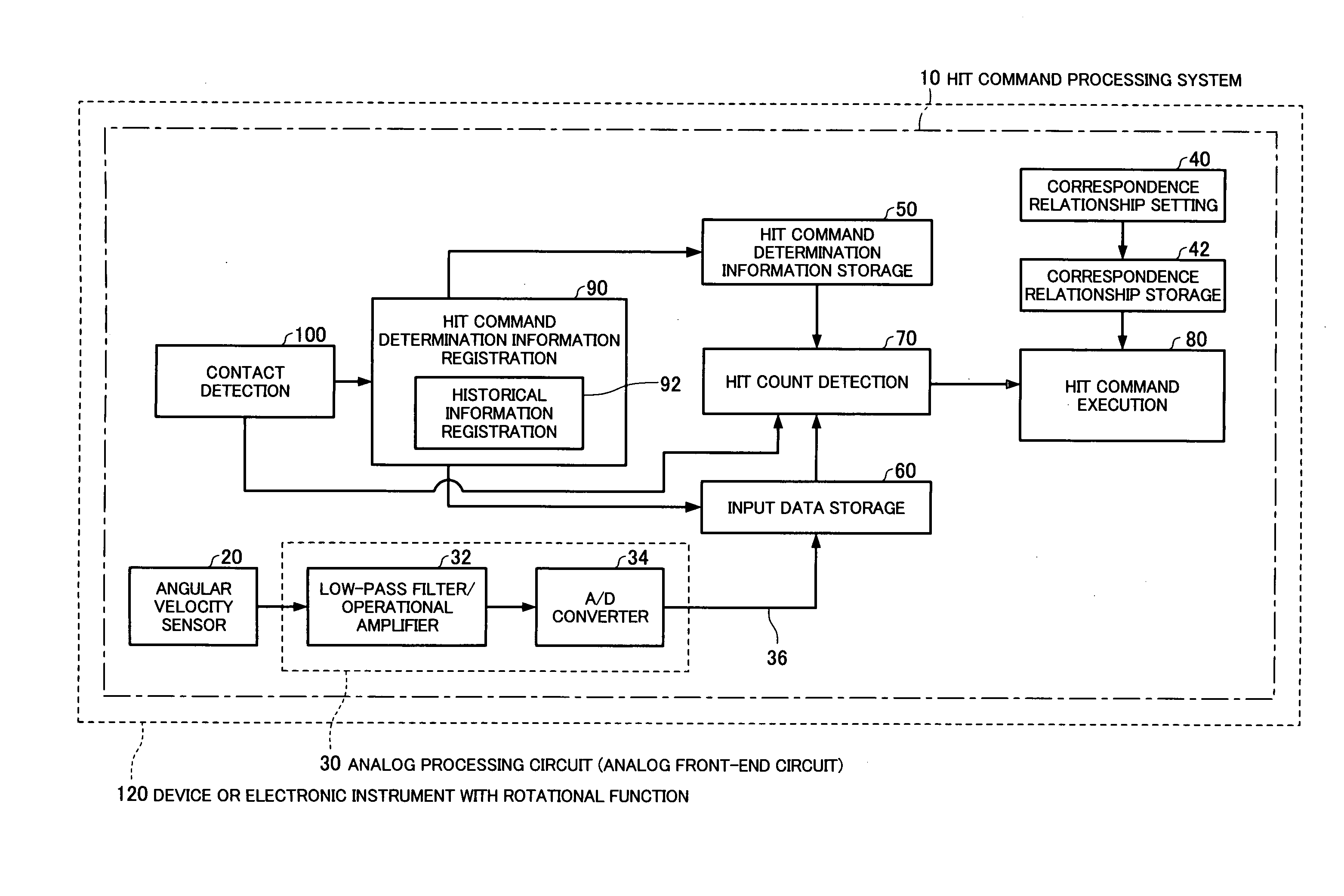
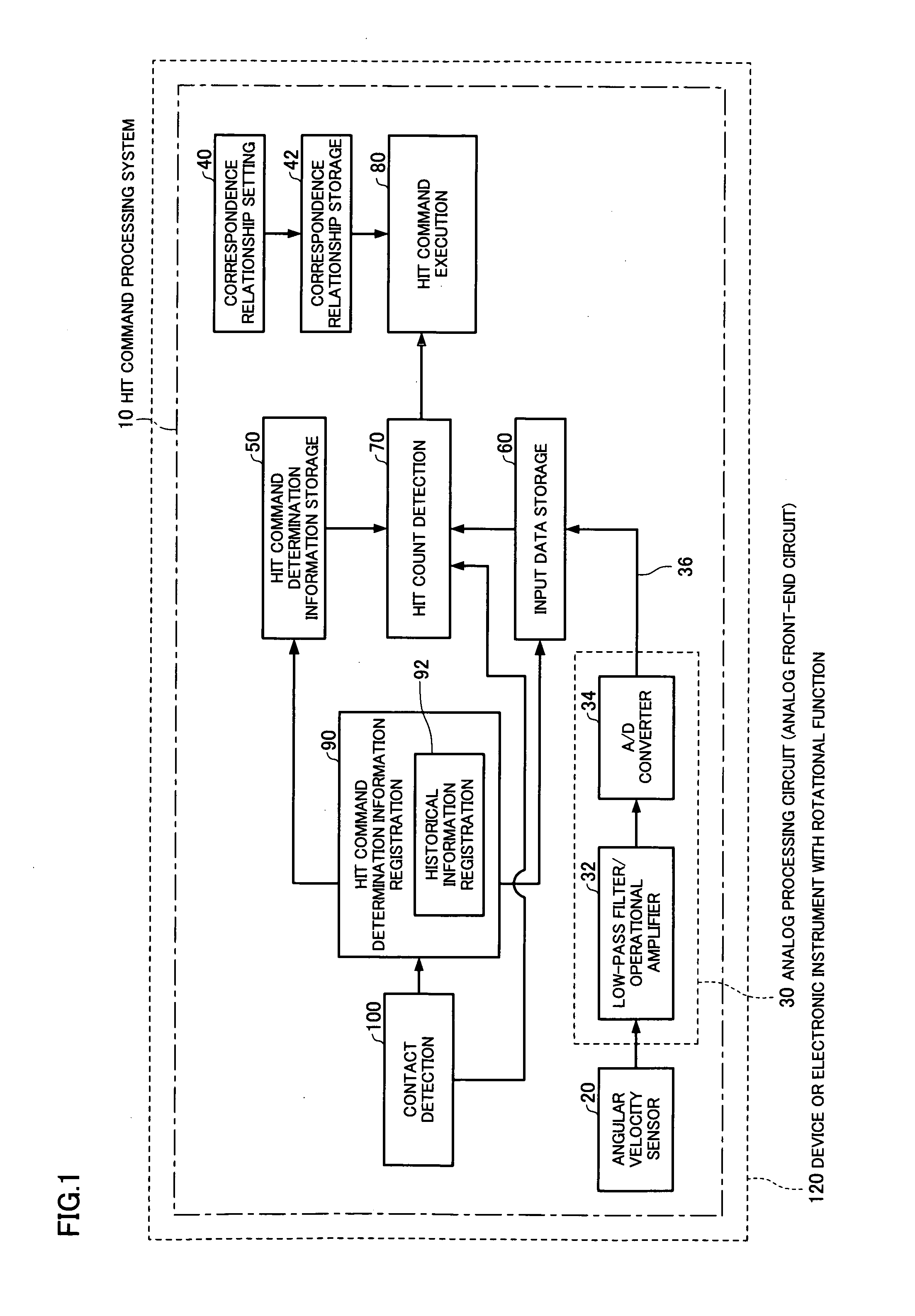
[0142]FIG. 1 is a diagram illustrative of a configuration of a hit command processing system according to one embodiment of the invention.

[0143]A hit command processing system 10 according to this embodiment includes an angular velocity sensor (gyrosensor) 20 as a vibration detection sensor. The angular rate sensor 20 measures a rotational velocity (rotational angular velocity) with respect to a rotation motion around a specific rotation axis, and outputs an analog signal 22 corresponding to the rotational angular velocity. The angular velocity sensor 20 may be a gyrosensor, for example. The gyrosensor may be a vibrating gyroscope which operates utilizing a piezoelectric effect, for example. In this type of gyrosensor, an alternating-current voltage is applied to an gyro-element (vibrator such as rock crystal) to cause the gyro-element to at least partially vibrate, and a current (voltage) corresponding to the rotation rate or the angular velocity is generated uti...

second embodiment

2. Second Embodiment

[0237]FIG. 15 is a diagram illustrative of a configuration of a hit command processing system according to a second embodiment.

[0238]A hit command processing system 610 according to this embodiment includes an angular velocity sensor (gyrosensor) 20 as a vibration detection sensor. The angular rate sensor 620 measures a rotational velocity (rotational angular velocity) with respect to a rotational motion around a specific rotation axis, and outputs an analog signal 22 corresponding to the rotational angular velocity. The angular velocity sensor 620 may be a gyrosensor, for example. The type of gyrosensor is arbitrary. For example, a gyrosensor utilizing a microelectromechanical system (MEMS) technology may be used. The rotational angular velocity with respect to a given axis may be detected, or may be detected with respect to three axes which intersect perpendicularly.

[0239]The hit command processing system 610 according to this embodiment includes an analog proc...


PUM


Abstract

A hit command processing system for an electronic instrument includes: an angular velocity sensor; an analog processing circuit which receives the analog signal output from the angular velocity sensor, converts the analog signal into a digital signal, and outputs the digital signal as a rotational angular velocity value; a hit input detection section which receives the rotational angular velocity value output from the analog processing circuit, and determines whether or not a hit input is performed to an electronic instrument based on a change in the rotational angular velocity value; and a hit command execution section which executes a command associated with the hit input when the hit input detection section has determined that the hit input has been performed.

Description

[0001]Japanese Patent Application No. 2007-105558, filed on Apr. 13, 2007, Japanese Patent Application No. 2007-23314, filed on Feb. 1, 2007, and Japanese Patent Application No. 2007-304533, filed on Nov. 26, 2007, are hereby incorporated by reference in their entirety.BACKGROUND OF THE INVENTION[0002]The present invention relates to a hit command processing system, an operation system for an electronic instrument, and an electronic instrument.[0003]A gyrosensor measures a rotational velocity (rotational angular velocity) with respect to a rotational motion around a specific rotation axis. A vibrating gyrosensor which detects a rotational angular velocity utilizing a Coriolis force is widely used at present.[0004]In a vibrating gyroscope which operates utilizing a piezoelectric effect, a Coriolis force occurs when applying an alternating-current voltage to a gyro-element (e.g., vibrator such as rock crystal), and a current is generated depending on the rotation rate or angular veloc...

Claims


Application Information

Patent Timeline
IPC IPC(8): G01P9/00G01H11/00
CPCG10H1/0008G10H2230/015G10H2220/395G10H2220/261
Inventor KAWAGUCHI, KAZUO
Owner SEIKO EPSON CORP
Learn More