
Control Mechanism for Controlling Width of Two Cutting Blades

a control mechanism and cutting blade technology, applied in the field of pruning scissors, can solve the problems of further affecting the quality and ease of pruning operation, and achieve the effect of quick adjustment and control of the open width of the scissors

Inactive Publication Date: 2008-08-07
NUSHARP
View PDF7 Cites 29 Cited by
  • Summary
  • Abstract
  • Description
  • Claims
  • Application Information

AI Technical Summary

Benefits of technology

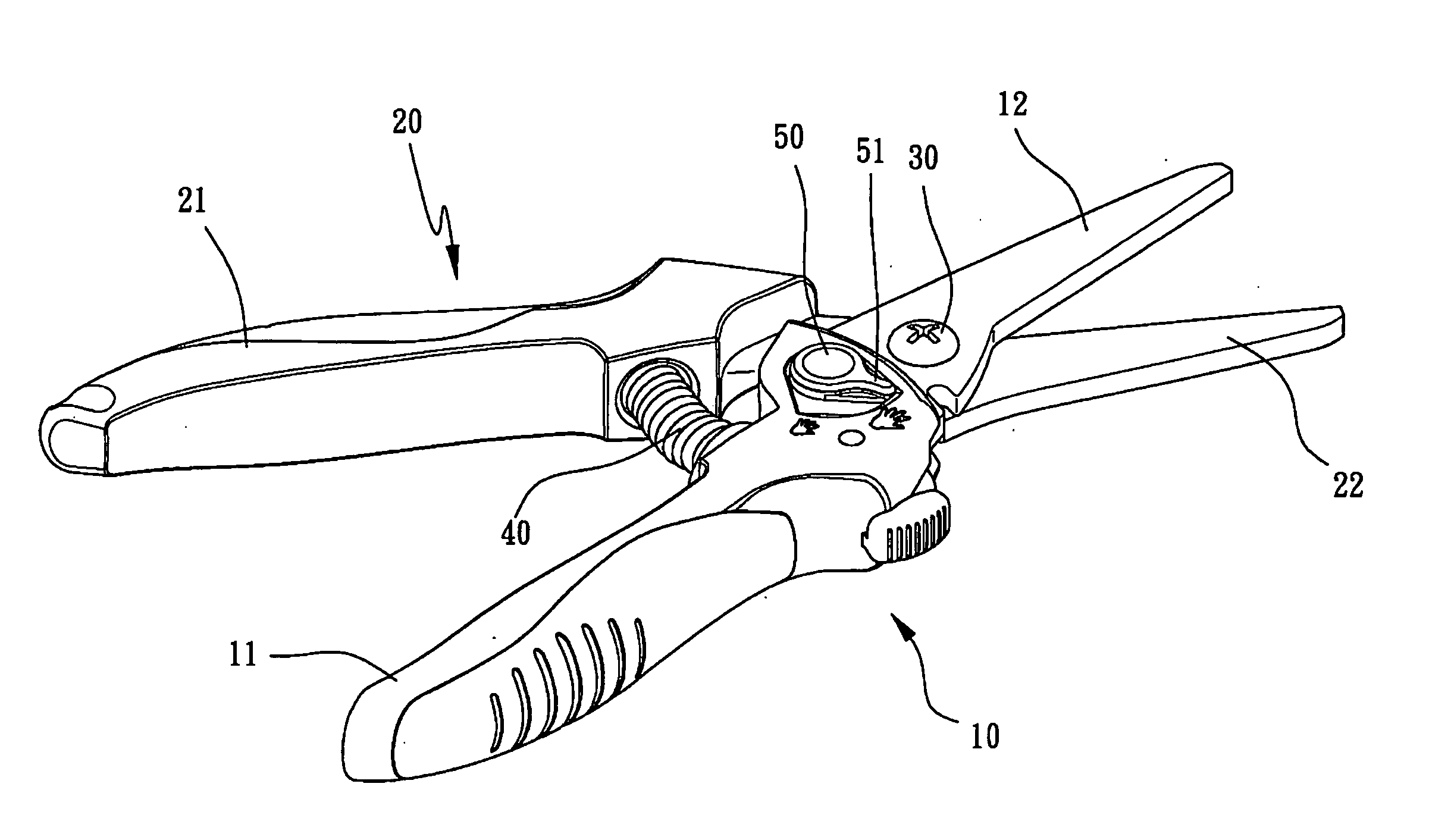
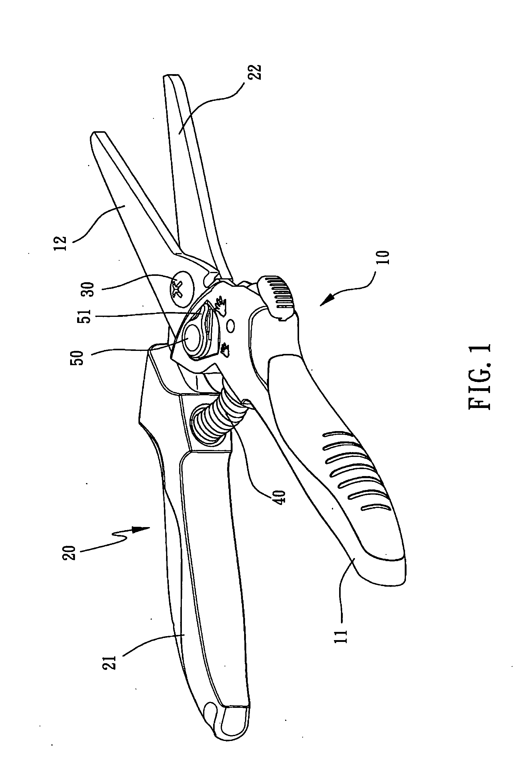
[0006]The primary object of the present invention is to provide a control mechanism for controlling width between two cutting blades of a pair of pruning scissors, wherein a control member is disposed at one side of the pin of the scissors and used to engage with a stop, the rotation of the control member makes different portions of the control member engage with the stop engage, producing thickness difference, so that the open width of the scissors can be quickly adjusted and controlled.

Problems solved by technology

The locking device only provides the user the options of fully opening or fully closing the scissors, and is unable to adjust the open width of the scissors to better fit different user's palm, thus further affecting the quality and easiness of the pruning operation.

Method used


Image

  • Control Mechanism for Controlling Width of Two Cutting Blades
  • Control Mechanism for Controlling Width of Two Cutting Blades
  • Control Mechanism for Controlling Width of Two Cutting Blades

Examples


Embodiment Construction

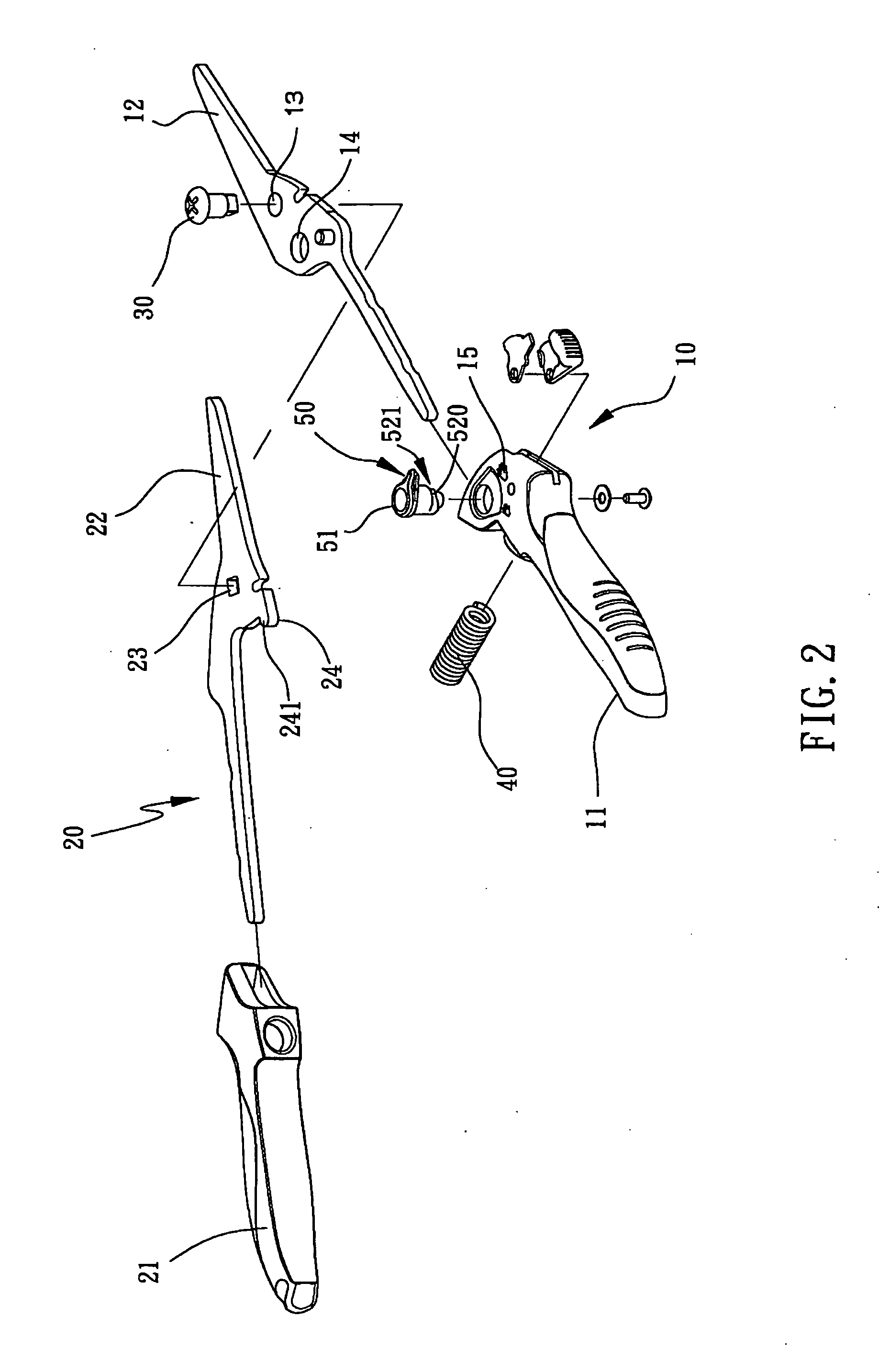
[0015]Referring to FIGS. 1 to 3, a pair of scissors of in accordance with the present invention comprises a first part 10, a second part 20, a pin 30, a spring 40, and a control member 50. The first part 10 has a first handle 11 which can be a grip mounted to the first handle 11, and a first blade 12 which is connected to an end of the first handle 11. A first pivotable hole 13 is defined in the first part 10 and located between the first handle 11 and the first blade 12. The first part 10 has a connection hole 14 which is located closer to the first handle 11 than the first pivotable hole 13.

[0016]The second part 20 has a second handle 21 which can be a grip mounted to the second handle 21, and a second blade 22 which is connected to an end of the second handle 21. A second pivotable hole 23 is defined in the second part 20 and located between the second handle 21 and the second blade 22. The pin 30 extends through the first and second pivotable holes 13, 23 so as to pivotably conn...


PUM


Abstract

A pair of scissors includes a first part which is pivotably connected to a second part. A stop extends from an inside of the second part. A control member rotatably extends through a connection hole in the first part and includes a plurality of engaging surfaces which have different radial heights so that the stop is engaged with one of the engaging surfaces to set the desired width between two blades of the first and second parts.

Description

[0001]This application is a continuation of part of U.S. patent application Ser. No. 11 / 066,473, which claims the benefit of the earlier filing date of Feb. 28, 2005. claim 1 of this application is the combination of the previous claims 1, 4 and 5 of the U.S. patent application Ser. No. 11 / 066,473, claims 2 and 9 of this application are the previous claims 3 and 7 of the U.S. patent application Ser. No. 11 / 066,473, and claims 3-8 of the application are new.FIELD OF THE INVENTION[0002]The present invention relates to a pair of pruning scissors, and more particularly to a control mechanism for controlling width between two cutting blades of pruning scissors, wherein the mechanism is located between the two handles and includes multiple controlling stages.BACKGROUND OF THE INVENTION[0003]A conventional pair of pruning scissors with a lock device is disclosed in U.S. Pat. No. 6,418,626, the two pivotally connected cutting blades of the scissors are defined with a locking hole and a step...

Claims


Application Information

Patent Timeline
Patent Type & Authority Applications(United States)
IPC IPC(8): B26B13/00
CPCB26B13/22A01G3/02B26B13/16
Inventor JOU, TITAN
Owner NUSHARP
Learn More