Structural mounting insert

a technology for mounting inserts and structural parts, applied in the direction of roofs, doors, hinges, etc., can solve the problems of limiting the ability of members to be attached to each other, limiting the ability of members to seal and/or degrade materials, and material drawbacks

Inactive Publication Date: 2008-07-31
ZEPHYROS INC
View PDF25 Cites 40 Cited by
  • Summary
  • Abstract
  • Description
  • Claims
  • Application Information

AI Technical Summary

Problems solved by technology

Such materials, however, suffer from drawbacks.
As one example, expansion/contraction characteristics of the materials during exposure to temperature variances can limit the ability of the materials to seal

Method used


Image

  • Structural mounting insert
  • Structural mounting insert
  • Structural mounting insert

Examples


Embodiment Construction

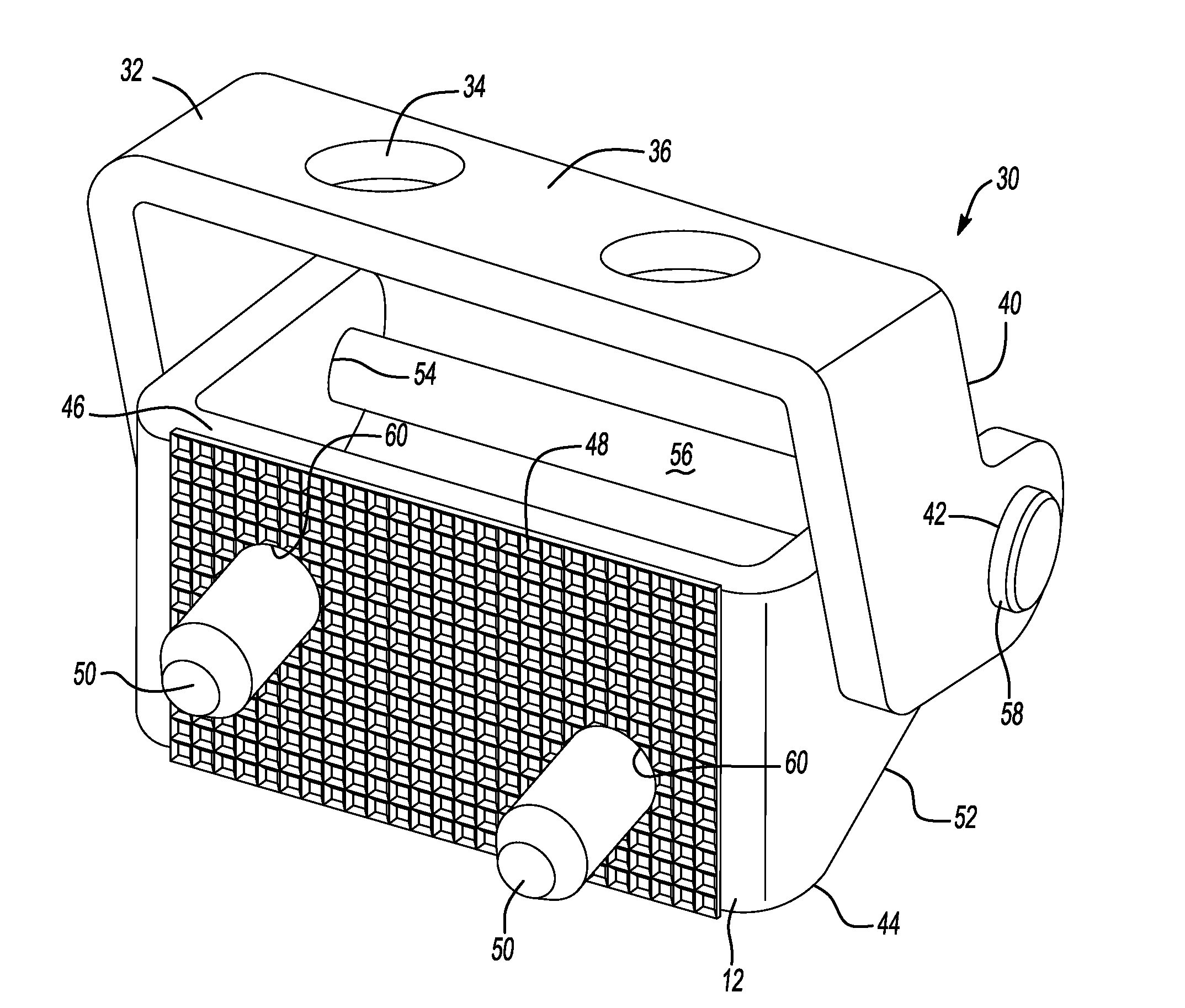
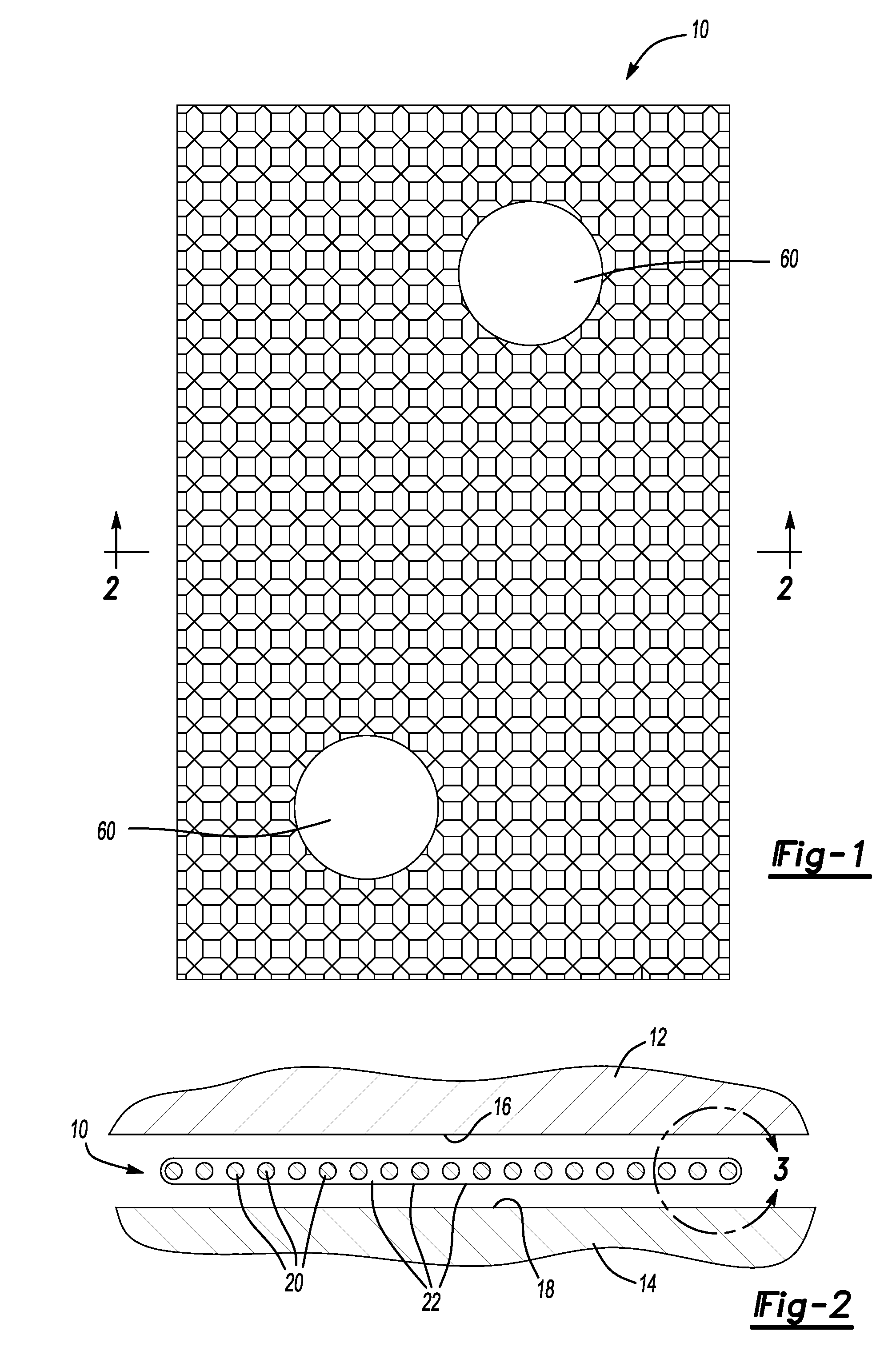
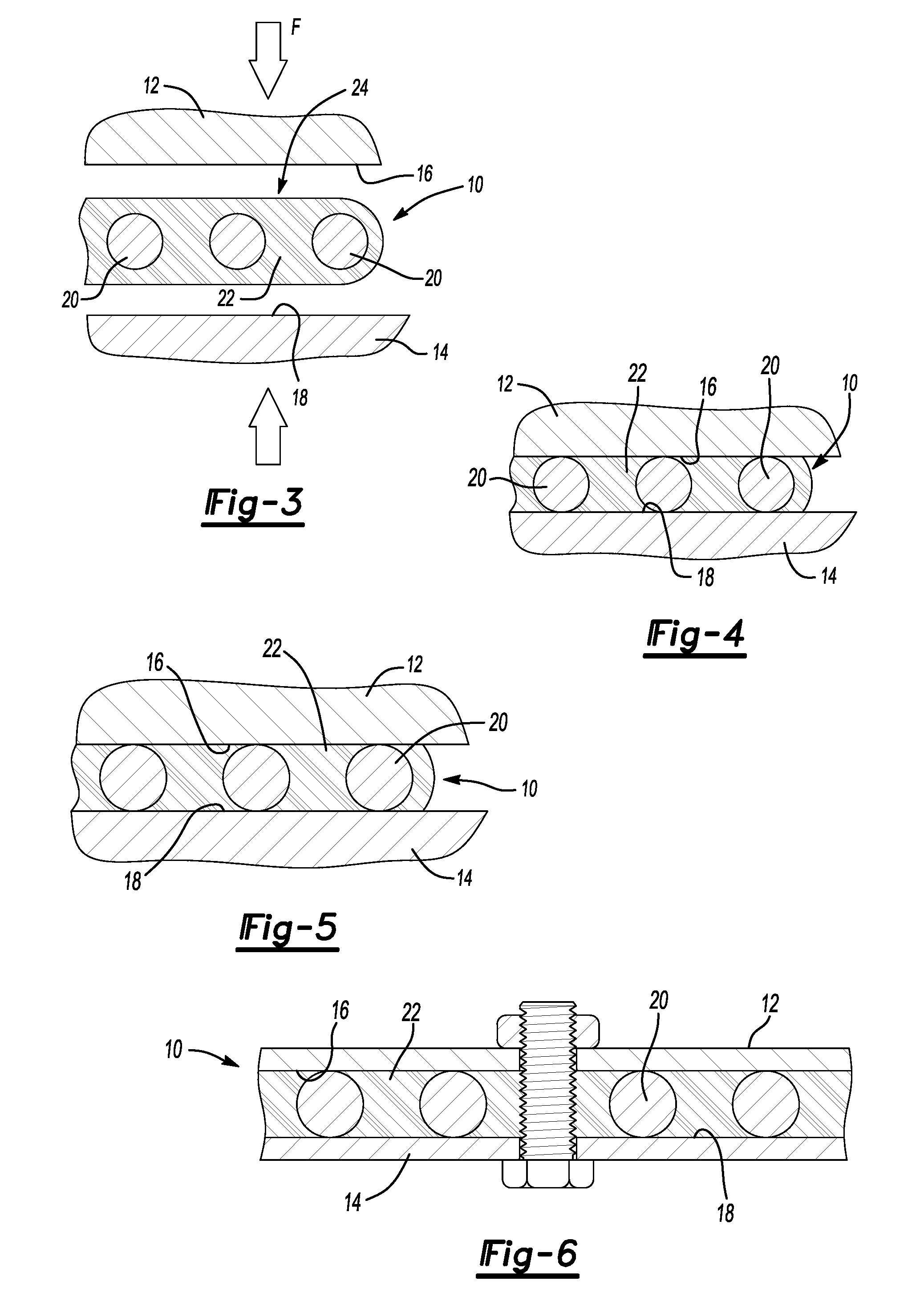
[0022]The present invention is predicated upon methods and devices for positively mounting structural members while preventing or substantially limiting exposure of such members to environmental conditions possibly leading to corrosion. Referring to the drawings, this is achieved through the use of an insert 10 placed between a first and second member 12, 14, respectively, prior to joining of the same. The insert includes a positive locating feature for maintaining a distance between the first and second member and a sealer that may be configured to fill open space between the first and second member, surround the insert and joining portions of the first and second members with the insert, or both. The sealer may be activatable, pliable or both to seal both the insert and the contacting portions 16, 18 of the structural members from the surrounding environment.

[0023]An additional advantage of the present invention is that it substantially limits or prevents torque fall off or the lo...


PUM


Abstract

A structural mounting insert for sealing between and/or adhering to surfaces of members is described. The insert includes a base member and activatable material about the base material.

Description

CLAIM OF PRIORITY[0001]The present application claims the benefit of the filing dates of U.S. Provisional Application Ser. No. 60 / 887,287, filed Jan. 30, 2007 and U.S. Provisional Application Ser. No. 60 / 951,327, filed Jul. 23, 2007, both of which are hereby incorporated by reference for all purposes.FIELD OF THE INVENTION[0002]The present invention relates to a methods and devices for the protection of two or more joined components from corrosion, loosening of fasteners (e.g., torque fall off) or both.BACKGROUND OF THE INVENTION[0003]For many years, industry has developed sealing materials and structural materials that can be located between surfaces of members for limiting exposure of those surfaces to ambient environments and / or for assisting in connecting the surfaces together. Such materials, however, suffer from drawbacks. As one example, expansion / contraction characteristics of the materials during exposure to temperature variances can limit the ability of the materials to se...

Claims


Application Information

Patent Timeline
IPC IPC(8): B60J5/00B32B3/10
CPCE05D5/02E05Y2600/526Y10T428/24331F16B11/006F16J15/068E05Y2800/12C09J5/00F16J15/06
Inventor COON, THOMAS L.ZDROJEWSKI, STEVENOVAK, KEITH
Owner ZEPHYROS INC
Why Eureka
Try Eureka