Suspension rack for screwdriver

a screwdriver and suspension rack technology, applied in the field of suspension racks, can solve the problems of increasing consumption costs and wasting suspension racks, and achieve the effect of reducing consumption costs and/or avoiding disadvantages

Inactive Publication Date: 2008-07-31
YIH CHENG FACTORY
View PDF0 Cites 15 Cited by
  • Summary
  • Abstract
  • Description
  • Claims
  • Application Information

AI Technical Summary

Benefits of technology

[0005]The present invention is to mitigate and / or obviate the disadvantage of the conventional suspension rack for screwdrivers.
[0006]The primary objective of the present invention is to provide a suspension rack for screwdrivers, wherein the reduced neck of the handle of each of the screwdrivers is limited between the respective limit slot of the first plate and the respective passage of the second plate of the support seat, so that each of the screwdrivers is limited by the support seat, thereby preventing each of the screwdrivers from being detached from the support seat freely so as to achieve a temporary anti-theft effect.
[0007]Another objective of the present invention is to provide a suspension rack for screwdrivers, wherein the screwdrivers can be removed from the support seat after the support seat is detached from the main board for use with the user, so that the user can choose the desired screwdrivers without having to buy all of the screwdrivers and the suspension rack, thereby reducing the costs of consumption.
[0008]A further objective of the present invention is to provide a suspension rack for screwdrivers, wherein the end portion of the handle of each of the screwdrivers is rested on and supported by the first plate of the support seat, and the shank of each of the screwdrivers is extended through the respective limit slot of the first plate and the respective passage of the second plate of the support seat to facilitate the user selecting and operating the screwdrivers.
[0009]A further objective of the present invention is to provide a suspension rack for screwdrivers, wherein the suspension rack comprises a plurality of support seats to increase the number of the screwdrivers, thereby facilitating the user operating the screwdrivers.

Problems solved by technology

However, the user has to buy all of the screwdrivers attached to the suspension rack and cannot select the desired screwdrivers according to the practical requirement, thereby greatly increasing the costs of consumption.
In addition, the user has to break the suspension rack to take out the screwdrivers, so that the suspension rack is useless after removing of the screwdrivers, thereby wasting the suspension rack.

Method used


Image

  • Suspension rack for screwdriver
  • Suspension rack for screwdriver
  • Suspension rack for screwdriver

Examples


Embodiment Construction

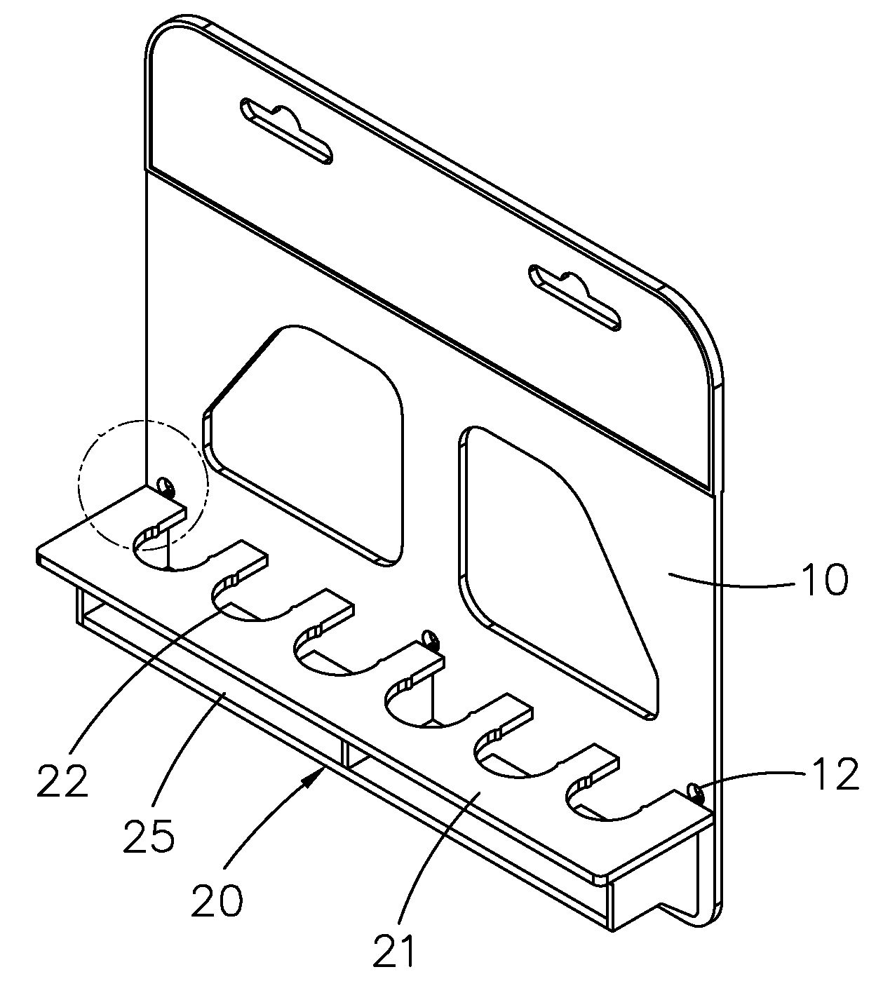
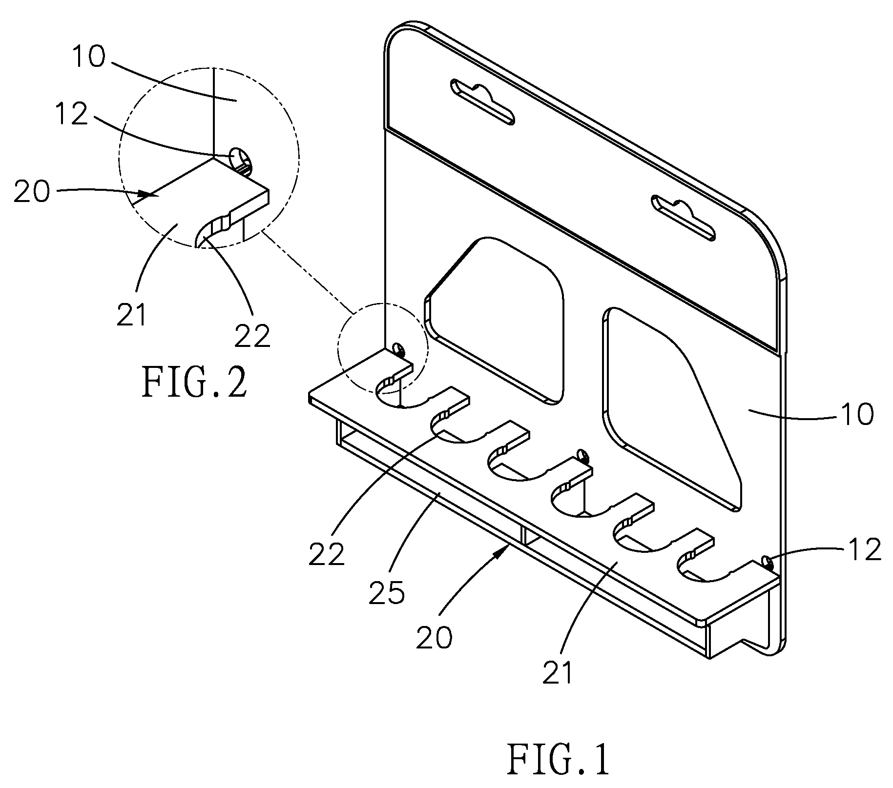
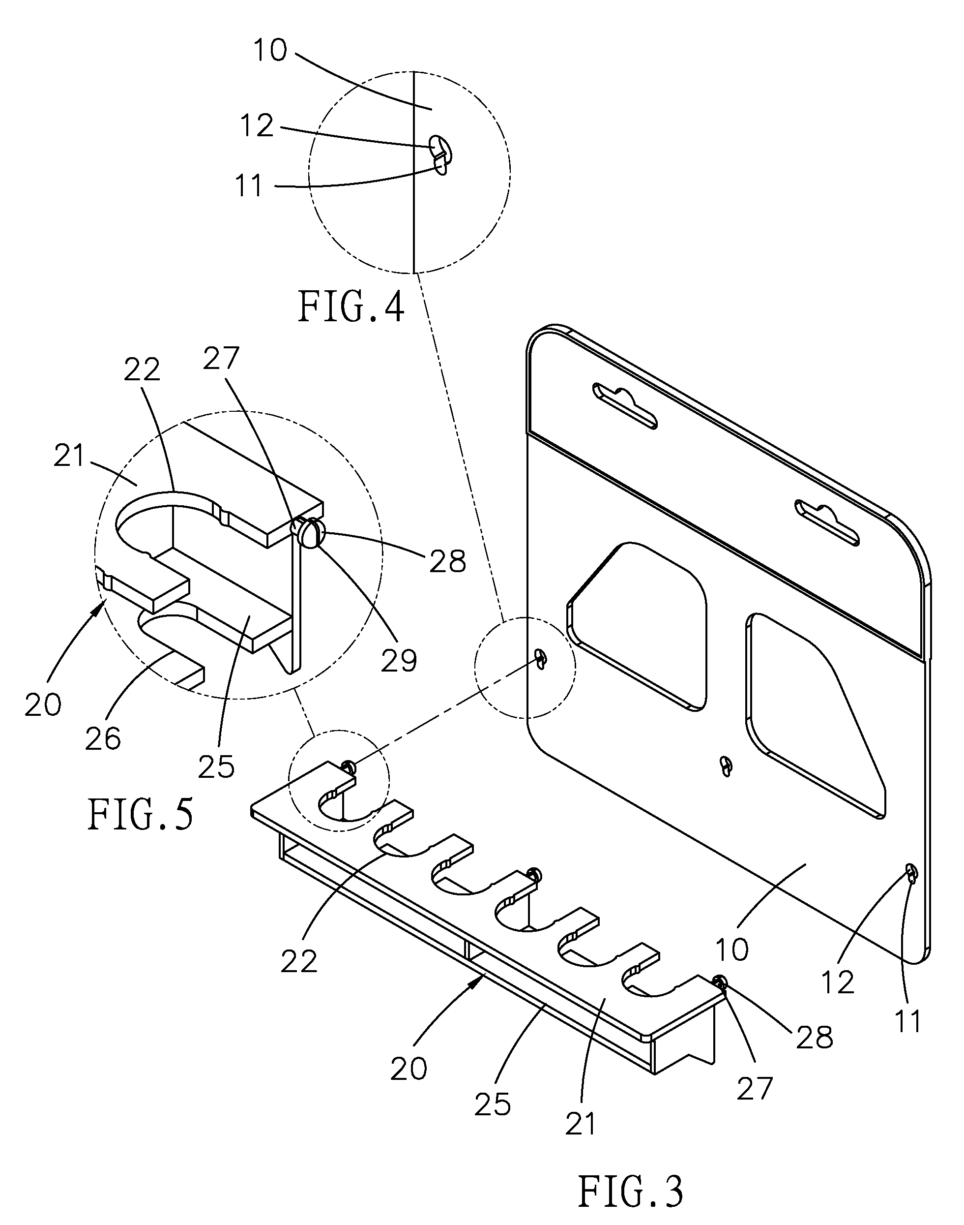
[0025]Referring to the drawings and initially to FIGS. 1-9, a suspension rack in accordance with the preferred embodiment of the present invention comprises a main board 10, at least one support seat 20 detachably mounted on a surface of the main board 10 and having a first plate 21 formed with a plurality of limit slots 22 and a second plate 25 spaced from the first plate 21 and formed with a plurality of passages 26 each aligning with a respective limit slot 22 of the first plate 21, and a plurality of screwdrivers 30 each having a handle 31 supported by the first plate 21 of the support seat 20, a reduced neck 32 limited in a respective limit slot 22 of the first plate 21 and a shank 35 extended through a respective passage 26 of the second plate 25 of the support seat 20.

[0026]The main board 10 is formed with a plurality of insertion holes 12 and a plurality of locking holes 11 each connected to a respective insertion hole 12. Each of the locking holes 11 of the main board 10 is...


PUM


Abstract

A suspension rack includes a main board, at least one support seat detachably mounted on the main board and having a first plate formed with a plurality of limit slots and a second plate formed with a plurality of passages, and a plurality of screwdrivers each having a handle supported by the first plate, a reduced neck limited in a respective limit slot and a shank extended through a respective passage. Thus, the reduced neck of each of the screwdrivers is limited between the respective limit slot and the respective passage, so that each of the screwdrivers is limited by the support seat, thereby preventing each of the screwdrivers from being detached from the support seat freely so as to achieve a temporary anti-theft effect.

Description

BACKGROUND OF THE INVENTION[0001]1. Field of the Invention[0002]The present invention relates to a suspension rack, and more particularly to a suspension rack for screwdrivers.[0003]2. Description of the Related Art[0004]A conventional suspension rack for screwdrivers comprises a main board, and a locking seat locked on a surface of the main board to attach a plurality of screwdrivers to the main board. Thus, the screwdrivers are locked solidly between the main board and the locking seat, thereby preventing the screwdrivers from being detached from the suspension rack freely and intentionally so as to achieve an anti-theft effect. However, the user has to buy all of the screwdrivers attached to the suspension rack and cannot select the desired screwdrivers according to the practical requirement, thereby greatly increasing the costs of consumption. In addition, the user has to break the suspension rack to take out the screwdrivers, so that the suspension rack is useless after removin...

Claims


Application Information

Patent Timeline
Patent Type & Authority Applications(United States)
IPC IPC(8): A47F7/00
CPCB25H3/04A47F7/0028
Inventor LIN, JACK
Owner YIH CHENG FACTORY
Why Eureka
Try Eureka