
Using zigzags to create three-dimensional embroidered structures

a three-dimensional embroidered structure and zigzag technology, applied in the field of surgical implants, can solve the problems of complex process, inconvenient mass production, and inability to achieve cost effective and repeatable mass production, and achieve the effect of cost effective and enhanced dome

Inactive Publication Date: 2008-07-31
NUVASIVE
View PDF99 Cites 29 Cited by
  • Summary
  • Abstract
  • Description
  • Claims
  • Application Information

AI Technical Summary

Benefits of technology

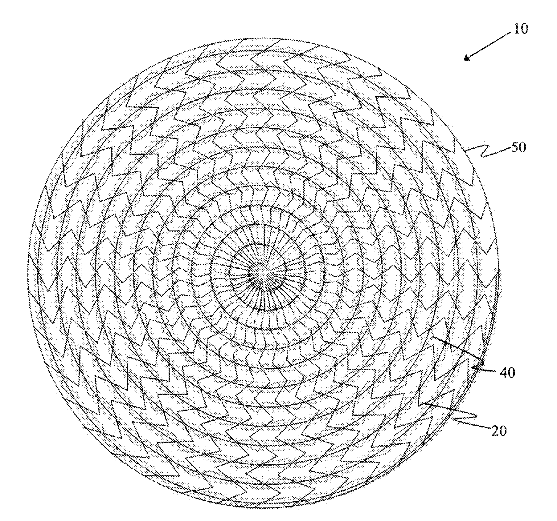
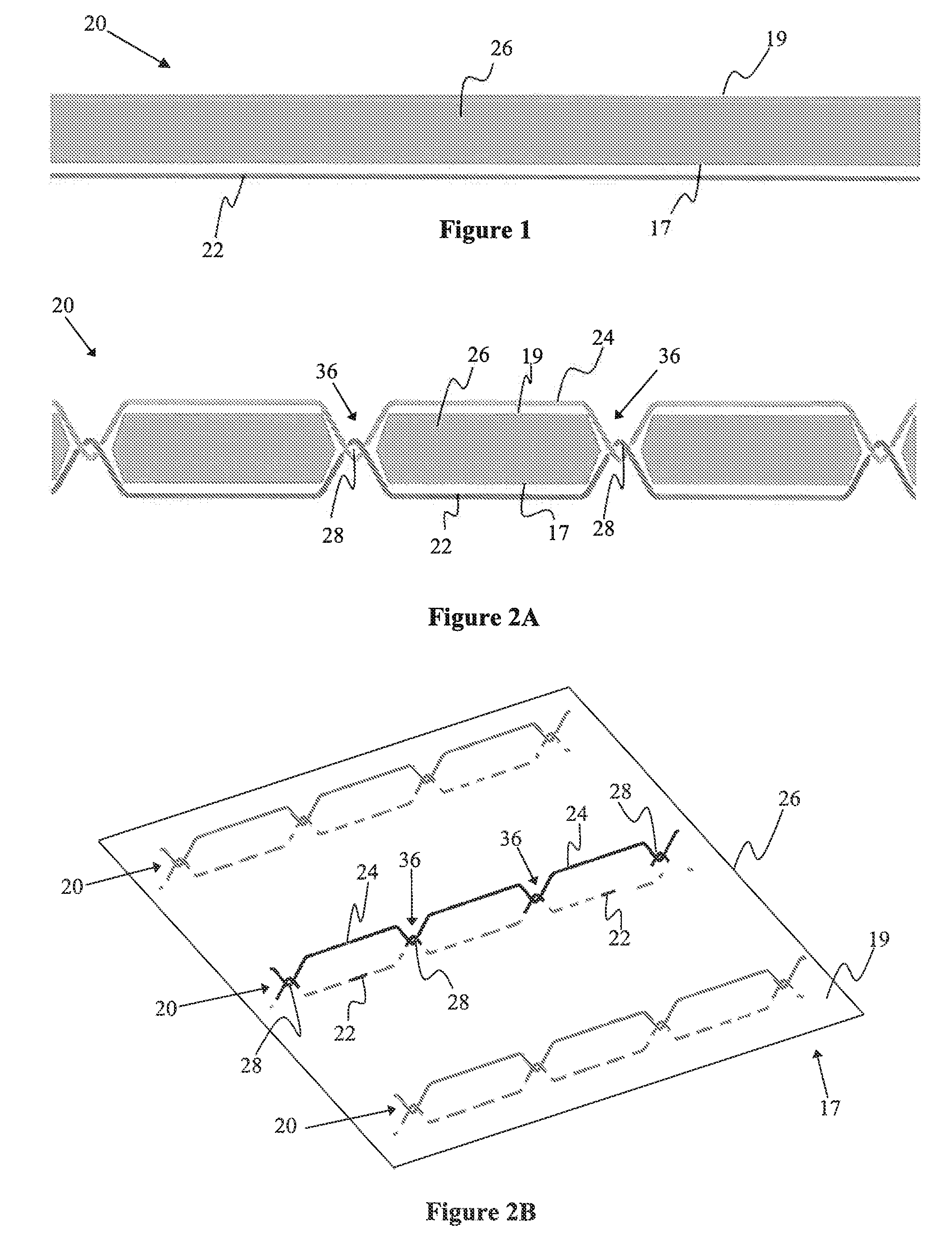
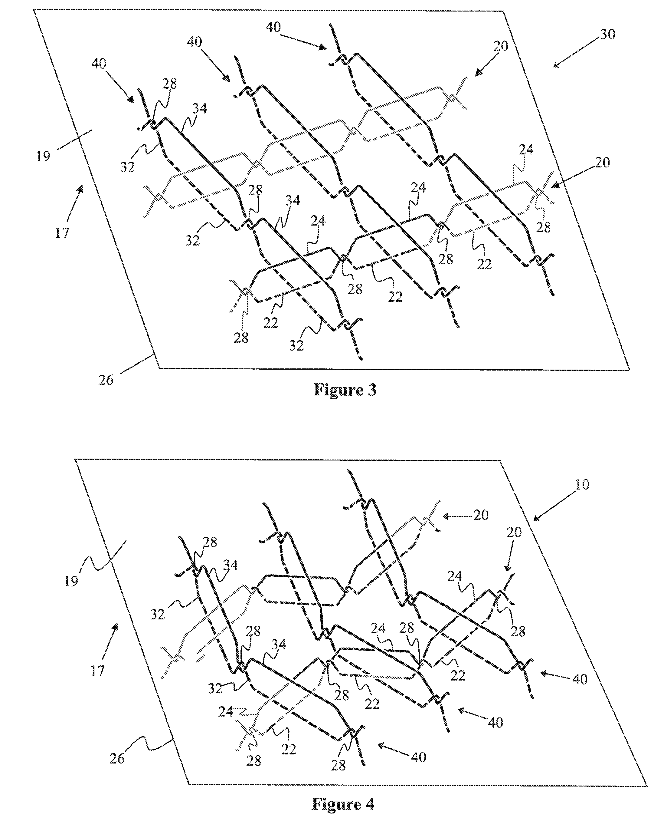
[0016]According to one embodiment, the present invention may include three-dimensional embroidered structures which may, by way of example only, be generally dome shaped. The three-dimensional embroidered structure may be achieved by stitching thread pairs and enclosing thread pairs, which form the embroidered structure, in paths longer than the shortest distance between the endpoints of each thread pair. This extra thread length may be laid down and stored on the dissolvable substrate upon which the embroidering may be done by stitching the thread pairs in a zigzagging or otherwise meandering path. Once the dissolvable substrate is removed, the extra thread pair length relaxes from the zigzag path into a straight run of thread. This relaxation causes the two-dimensional zigzagging thread pair to become a three-dimensional structure-dependent shape, e.g. straight, curved, arcuate, or any combination thereof, as the length stored in the zigzagging path between its two fixed endpoints is conserved in the length between the same two fixed endpoints.
[0017]By way of example only, the summation of all the structure-dependent shaped thread pairs may form a dome-shaped embroidered structure. This dome effect may be enhanced by adding straight embroidered threads around the outside borders of the zigzagged area or, if the zigzagged area is surrounded by a uniform straight mesh, then around those borders. This straight embroidered thread border may be rigid and thus may prevent the zigzagged embroidered threads from expanding radially and thereby force them into a more pronounced dome shape.

Problems solved by technology

There are, however, applications where it would be advantageous to have a generally three-dimensional embroidered structure rather than a generally two-dimensional embroidered structure, but the processes by which three-dimensional embroidered structures may be formed have been complicated and not conducive to cost effective and repeatable mass production.
The drawbacks to this technique are: it makes the embroidered structure thicker where the building up has been done; the building up only yields block-type structures and does not allow for the embroidering of curvatures; and this layering process must be done three-dimensionally, which excludes the use of a cost effective, repeatable form of mass production such as an automated embroidery machine.
This process is costly with repeatability concerns where the final results and dimensions will be subject to the skill and dexterity of the individual who performs the stitching.
However, this process suffers from the same post-embroidering stitching steps in three-dimensions as the second process, and thus suffers from the same drawbacks.

Method used


Image

  • Using zigzags to create three-dimensional embroidered structures
  • Using zigzags to create three-dimensional embroidered structures
  • Using zigzags to create three-dimensional embroidered structures

Examples


Embodiment Construction

[0035]Illustrative embodiments of the invention are described below. In the interest of clarity, not all features of an actual implementation are described in this specification. It will of course be appreciated that in the development of any such actual embodiment, numerous implementation-specific decisions must be made to achieve the developers' specific goals, such as compliance with system-related and business-related constraints, which will vary from one implementation to another. Moreover, it will be appreciated that such a development effort might be complex and time-consuming, but would nevertheless be a routine undertaking for those of ordinary skill in the art having the benefit of this disclosure. The process of creating three-dimensional structures by embroidering with zigzagging thread pairs disclosed herein boasts a variety of inventive features and components that warrant patent protection, both individually and in combination.

[0036]FIG. 1 illustrates a backing thread...


PUM

PropertyMeasurementUnit
Structureaaaaaaaaaa
Biodegradabilityaaaaaaaaaa
Compatibilityaaaaaaaaaa

Abstract

An embroidery process allowing for extra lengths of stitched thread pairs to be laid down in a zigzag pattern while embroidering on a dissolvable substrate such that when the substrate is removed, the extra length allows the two-dimensional embroidered structure to relax into a three-dimensional shape.

Description

CROSS REFERENCES TO RELATED APPLICATIONS[0001]The present application is a nonprovisional patent application claiming benefit under 35 U.S.C. §119(e) from U.S. Provisional Application Ser. No. 60 / 898,892, filed on Jan. 31, 2007, the entire contents of which are hereby expressly incorporated by reference into this disclosure as if set forth fully herein.BACKGROUND OF THE INVENTION[0002]I. Field of the Invention[0003]The present invention relates to medical devices and methods generally aimed at surgical implants. In particular, the disclosed system and associated methods are related to a manner of creating surgical implants via embroidery.[0004]II. Discussion of the Prior Art[0005]Embroidered structures are created on substrates. Some substrates are designed to stay in place with the embroidered structure while other substrates are removed at the end of the embroidery process. All of the embroidered structures discussed below are created on removable substrates, specifically ones rem...

Claims


Application Information

Patent Timeline
IPC IPC(8): D05C17/00D05B3/04D05B3/00
CPCA61F2/0045D05C17/00A61F2210/0004A61F2/0063
Inventor BUTCHER, PETER
Owner NUVASIVE
Learn More