
Rapid exchange stent delivery catheter

a stent and stent technology, applied in the field of interventional catheters, can solve the problems of complicated task, increased difficulty in determining the length of the lesion, and limitations of imaging or visualization, and achieve the effects of tracking over the guidewire, rapid exchange, and improving the pushability of the distal portion of the balloon catheter

Inactive Publication Date: 2008-07-17
INNOVATIONAL HLDG LLC
View PDF3 Cites 54 Cited by
  • Summary
  • Abstract
  • Description
  • Claims
  • Application Information

AI Technical Summary

Benefits of technology

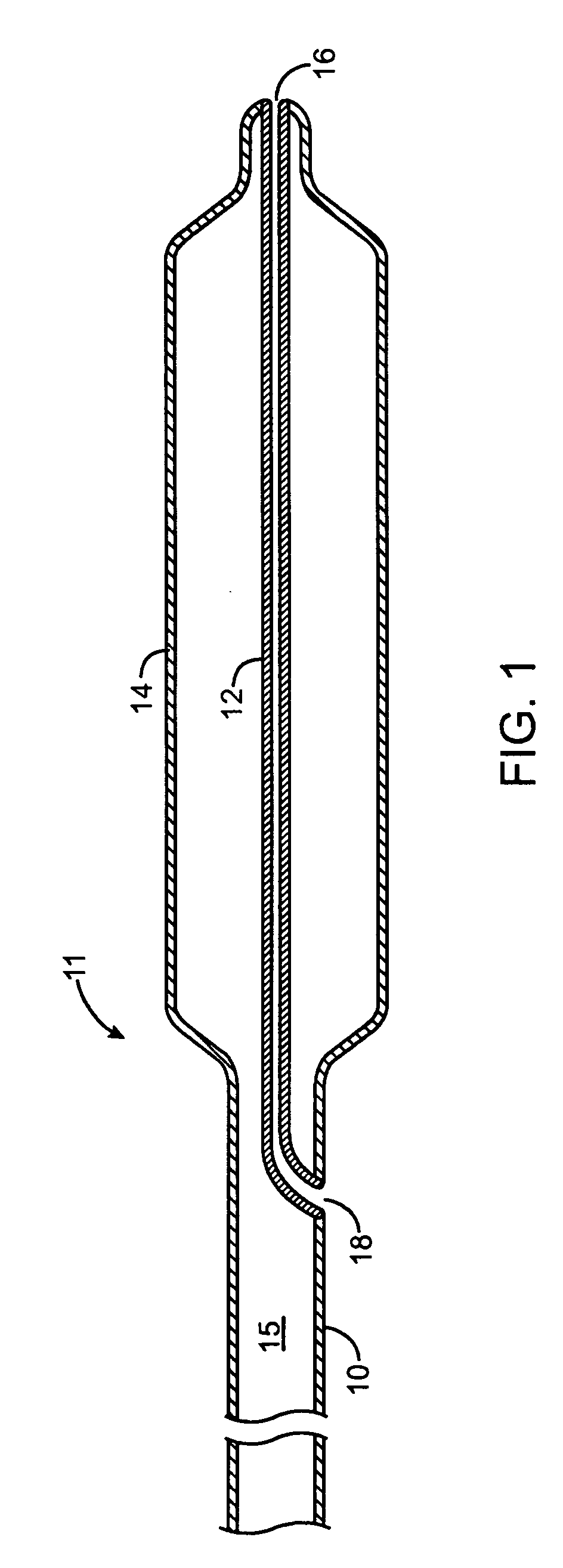
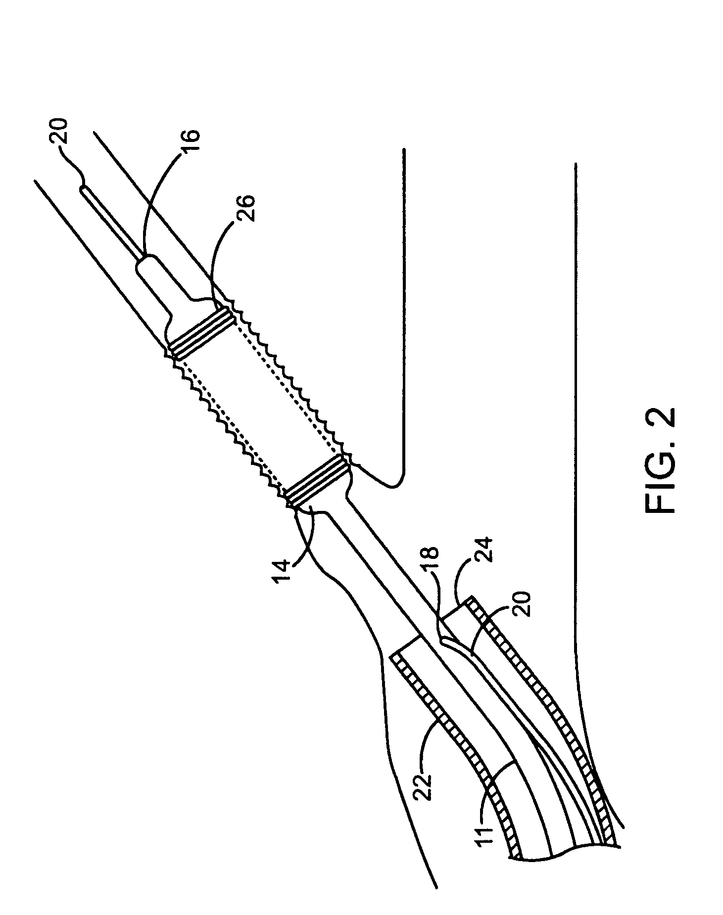
[0011]In accordance with the invention, the afore-mentioned deficiencies in the prior art are addressed by providing a stent delivery balloon catheter including a balloon leg having an extended length so that the bonding junction between the balloon and the catheter shaft is move proximally. In addition, a distance between a proximal guidewire ports and the distal end of the catheter is reduced from traditional rapid exchange catheters to achieve a move rapid termed super rapid exchange. In this manner, pushability of the distal portion of the balloon catheter and trackability over the guidewire are improved, while at the same time more rapid exchanged are possible. Improved pushability of the distal portion of the balloon catheter and trackability over the guidewire, and reduced possibilities of shaft bowing away from the guidewire, or guidewire looping can also be achieved by providing a stiffening wire, having several possible configurations, that extends at least partially along the length of the balloon leg and catheter shaft. In addition, to provide lesion dimension measurements, radiopaque marker bands are provided on the guidewire tube such that a visual frame of reference is available against which lesion measurements can be made in order to assist with proper stent or balloon selection.

Problems solved by technology

This task is complicated by limitations of imaging technology.
In most cases, imaging or visualization of a lesion is compromised by limitations of the viewing angle because the visualization system may not be positioned to provide a direct side view of the vessel.
The view in this instance is foreshortened because of the orientation of the visualization system relative to the vessel, making a determination of lesion length even more difficult.
This issue is further aggravated when curved vessels are involved, making length determination even more problematic.
However, such a dimension has been found to be problematic for several reasons.
However, flexibility must be balanced so as not to compromise the ability of the catheter to track over the guidewire, or permit bowing or looping of the catheter or other movement of the catheter away from the guidewire, resulting in loss of pushability.
Another issue relating to the flexibility of the distal portion of the catheter is due to the composition of the catheter.

Method used


Image

  • Rapid exchange stent delivery catheter
  • Rapid exchange stent delivery catheter
  • Rapid exchange stent delivery catheter

Examples


Embodiment Construction

[0022]FIG. 3 shows an assembly 30 including a rapid exchange stent delivery catheter 32, a guidewire 34, and a stent 36. The stent 36 is seated over an expandable portion 38 of a balloon 50 disposed in the distal portion of the catheter. The stent 36 is shown in an expanded state. In the unexpanded or delivery configuration, the expandable portion 38 of the balloon 50 and stent 36 will have an outer diameter close to the outer diameter of the shaft of the catheter 32 for easy maneuverability through the patient's vasculature.

[0023]As seen in FIG. 4, the expandable portion 38 is in fluid communication with a primary lumen 40 of the stent delivery catheter 32 defined by the generally tubular nature of the catheter shaft over substantially its entire length. The primary lumen 40 serves to deliver fluid, such as saline, to and from the expandable portion 38 to inflate or deflate the balloon. A secondary, guidewire tube 42 defining a secondary lumen 44 through which a guidewire (not show...


PUM


Abstract

A rapid exchange balloon catheter has a short rapid exchange length for faster catheter exchanges the balloon catheter includes a balloon structure having a balloon leg connected to a catheter shaft. Marker bands may be provided in the balloon leg for facilitating measurement of a dimension of physiological features. A stiffening wire extending longitudinally at least partially into the balloon leg may be provided to supplement and control the flexibility characteristics of the balloon leg.

Description

BACKGROUND OF THE INVENTION[0001]1. Field of the Invention[0002]The invention relates to interventional catheters, and more particularly, a rapid exchange stent delivery catheter.[0003]2. Brief Description of the Related Art[0004]Stent delivery catheters are known in the art. They generally comprise an elongated tubular device having a distal portion that carries a stent for delivery to a site in a patient's vasculature. The stent may be medicated and is used to prop open and support a constricted or otherwise compromised section of the blood vessel, due for example to arterial sclerosis. The stent is delivered in a contracted state so that it can be maneuvered through the vasculature. Once it is at the desired location, it is expanded and decoupled from the catheter. The delivery catheter is then withdrawn.[0005]The delivery catheter is provided with a balloon on which the stent is securely seated during delivery. When the stent reaches its destination, the balloon is inflated, cau...

Claims


Application Information

Patent Timeline
Patent Type & Authority Applications(United States)
IPC IPC(8): A61M29/00A61M31/00A61M37/00
CPCA61F2/958A61M2025/0183A61M25/10
Inventor BROWN, PETER S.VOSS, LAWRENCE JOHNLITVACK, FRANK
Owner INNOVATIONAL HLDG LLC
Learn More