Method and apparatus for controlling power in a decode-and-forward relay system
a relay system and relay technology, applied in the field of relay systems, can solve the problems of reducing the efficiency of power, affecting the accuracy of channel information, and insufficient technologies and experimental data in association with the communication of the relay system using the df relay scheme, so as to achieve accurate channel information.
- Summary
- Abstract
- Description
- Claims
- Application Information
AI Technical Summary
Benefits of technology
Problems solved by technology
Method used
Image


Examples
first embodiment
k Status
[0031]FIG. 2 illustrates a graph of a transmit signal power having PS and γ2P+(γ0−γ2)PS for x and y axes respectively in an infinite feedback status according to an exemplary embodiment of the present invention. Hereinafter, a method of calculating the range of an optimal transmit signal power at a source node in the infinite feedback status will be described with reference to FIG. 2.
[0032]Referring back to FIG. 1, a DF protocol, when a channel gain connecting a source node 110 and a relay node 120 is greater than another channel gain connecting a source node 110 and a destination node 130, i.e. γ1>γ0, the relay scheme helps the source transmission. Otherwise, the source node 110 transmits a signal to the destination node 130 without using the relay scheme. In this case, total mutual information indicates a minimum value between mutual information to a link from the source node 110 to the relay node 120, and mutual information to a link from the relay node 120 to the destina...
second embodiment
tatus
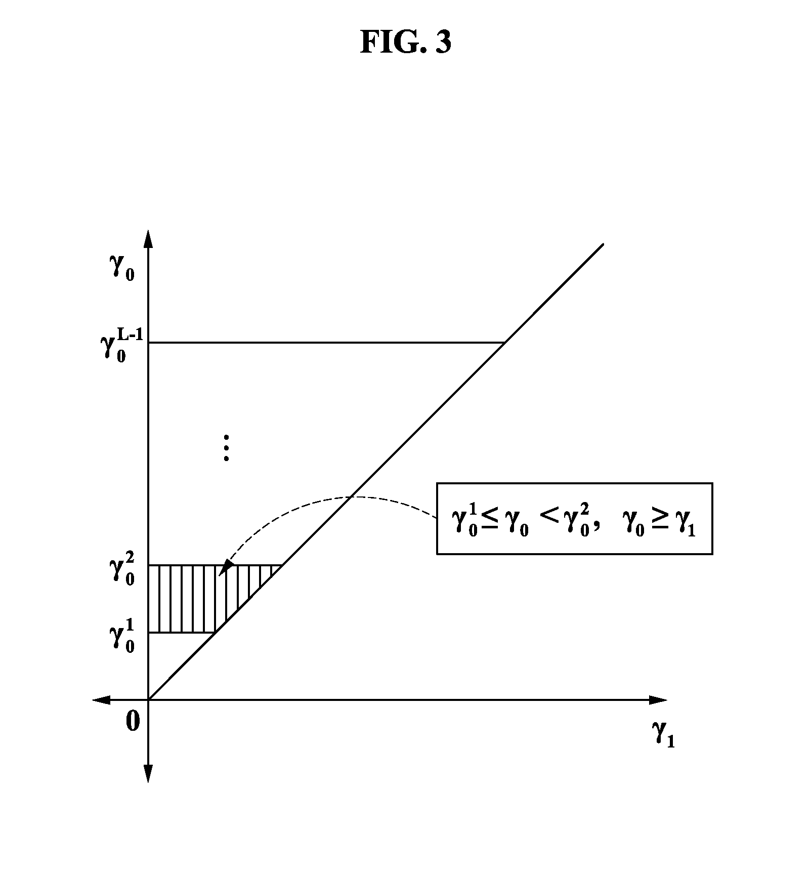
[0043]FIG. 3 illustrates a graph of a quantization region having γ1 and γ0 for x and y axes respectively in a finite feedback status according to an exemplary embodiment of the present invention, and FIG. 4 illustrates a graph of a quantization region having γ2 and γ0 for x and y axes respectively in a finite feedback status according to an exemplary embodiment of the present invention. Hereinafter, a method of calculating the range of an optimal transmit signal power at a source node in the finite status will be described with reference to FIGS. 3 and 4.
[0044]Information about γ0, γ1, and γ2 may be acquired by using a pilot signal.
[0045]Referring to FIG. 3, y axis is quantized with a predetermined number of integers. In this instance, when γ0>γ1, the relay node 120 is not required. Conversely, when γ01, a signal is transmitted via the relay node 120.
[0046]By considering the above-described factor, a shaded region shown in FIG. 4 is iteratively quantized. Different power is all...
third embodiment
[0060]The total transmit signal power P corresponds an addition of PS and Pr i.e. P=Ps+Pr. In this instance, Ps=κP, Pr=(1−κ)P, and κ has the range between 0 and 1. In a no feedback status, it is most important to acquire an appropriate κ to reduce an outage probability. An outage event where the outage status occurs corresponds to a union of, with γ0≧γ1 or γ0≧γ2, κγ0P≦K and with γ01 and γ02, γ1=γ0+γ2(1−κ) / κ≦K / P. Therefore, in the present exemplary embodiment, the optimal transmit signal power is acquired by,
Pout=∫0γ0*∫0γ0fγ0,γ1(γ0,γ1)γ1γ0+∫0γ0*∫0γ0fγ0,γ2(γ0,γ2)γ2γ0-P(γ0≥γ1,γ0≥γ2)+P(γ0<γ1)+∫0κγ1*∫γ0β(γ0)fγ0,γ2(γ0,γ2γ0<γ1)γ2γ0≈(λ1+λ2)(γ0*)2λ0λ1λ2+λ1λ0+λ1κ21-κ(γ1*)2λ0λ2[Equation8]
where β(x)=(γ1*−x)κ / (1−κ). In this instance, an approximation value corresponds to a high signal-to-noise ratio (SNR) value. Also, when substituting γ0*=K / (κP) and γ1*=K / P for Equation 8 above, optimal κ* is arranged to
(λ1)2κ4(κ−2)+2(λ0+λ1)(λ1+λ2)(1−κ)2=0 [Equation 9]
[0061]In Equation 9, it is possible ...
PUM
 Abstract
Description
Claims
Application Information
 - R&D
- Intellectual Property
- Life Sciences
- Materials
- Tech Scout
- Unparalleled Data Quality
- Higher Quality Content
- 60% Fewer Hallucinations
Browse by: Latest US Patents, China's latest patents, Technical Efficacy Thesaurus, Application Domain, Technology Topic, Popular Technical Reports.
© 2025 PatSnap. All rights reserved.Legal|Privacy policy|Modern Slavery Act Transparency Statement|Sitemap|About US| Contact US: help@patsnap.com