
Portable cutting device with guiding guard

a cutting device and guide guard technology, applied in the direction of metal sawing devices, sawing devices, sawing apparatuses, etc., can solve the problems of loss of efficiency, difficult handling, and exhaustion of users,

Inactive Publication Date: 2008-07-17
SPINATO DAVID
View PDF33 Cites 36 Cited by
  • Summary
  • Abstract
  • Description
  • Claims
  • Application Information

AI Technical Summary

Benefits of technology

[0008]The present invention responds the above mentioned need by proposing a portable cutting device with guiding guard th...

Problems solved by technology

Such manual tools present numerous disadvantages, among which are loss of efficiency, exhausting the user and imprecision of cutting.
These devices also present disadvantages and difficulties in that they are difficult to handle, unsuited for precision cuts, or lacking in efficiency.
For example, grinders having a circular grinding stone are used to grind objects, but are not suitable for cutting objects as they heat up the object when cutting, and present other difficulties and inefficiencies.
Such circular blades are often mounted to apparatuses or include a guard that present difficulties and inefficiencies by rendering the apparatus difficult to handle, complex, among other things.
However, the guards or guides known in the art of portable cutting devices have numerous disadvantages including inefficiency, imprecision, non-versatility and complexity.
This saw has certain disadvantages, however, when it comes to cutting certain types of objects.

Method used


Image

  • Portable cutting device with guiding guard
  • Portable cutting device with guiding guard
  • Portable cutting device with guiding guard

Examples


Embodiment Construction

[0025]In the following description, similar features in the drawings have been given same reference numerals and in order not to weigh down the Figs, some elements are not referred to in some Figs if they were already identified in a precedent Fig.

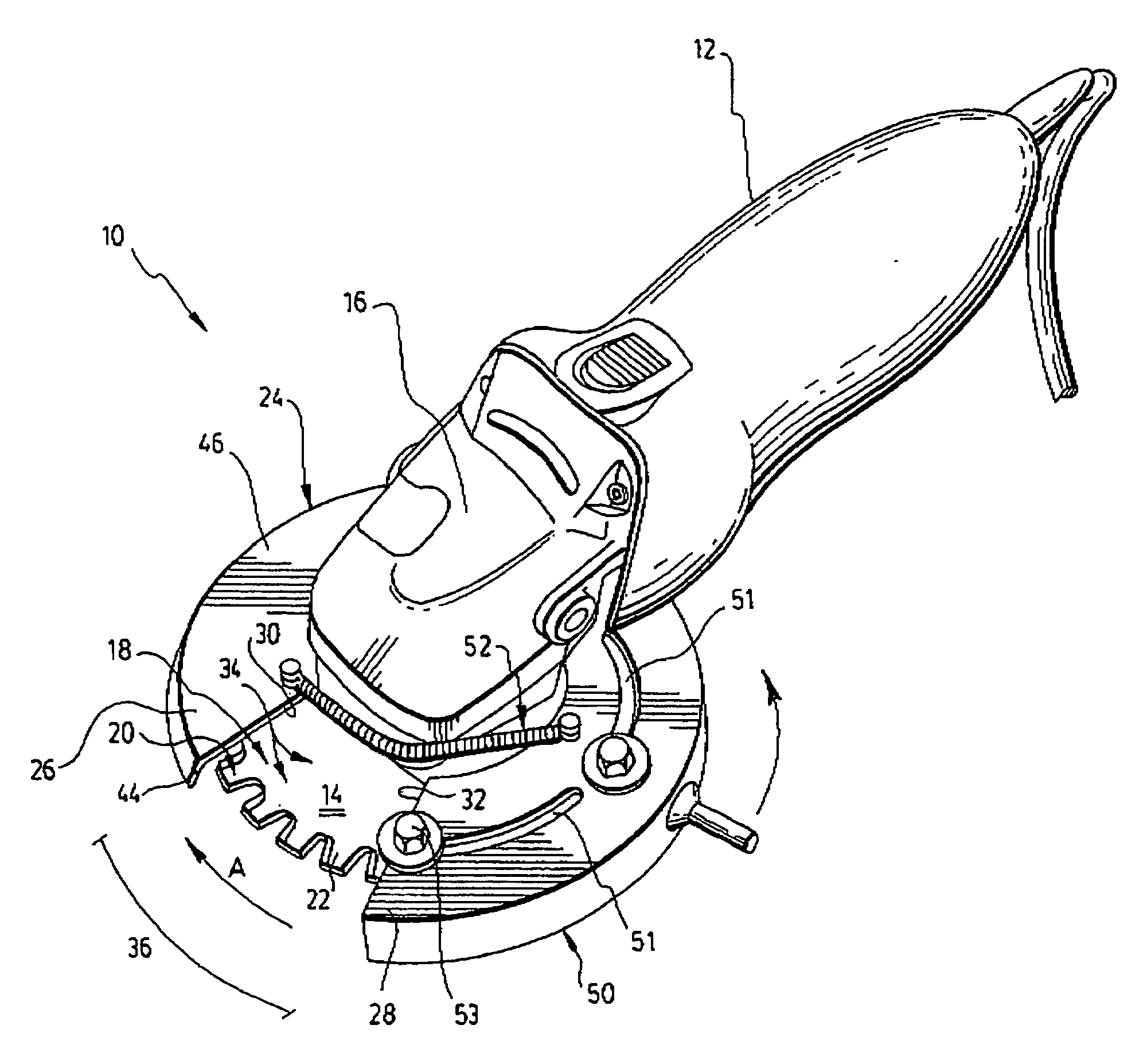
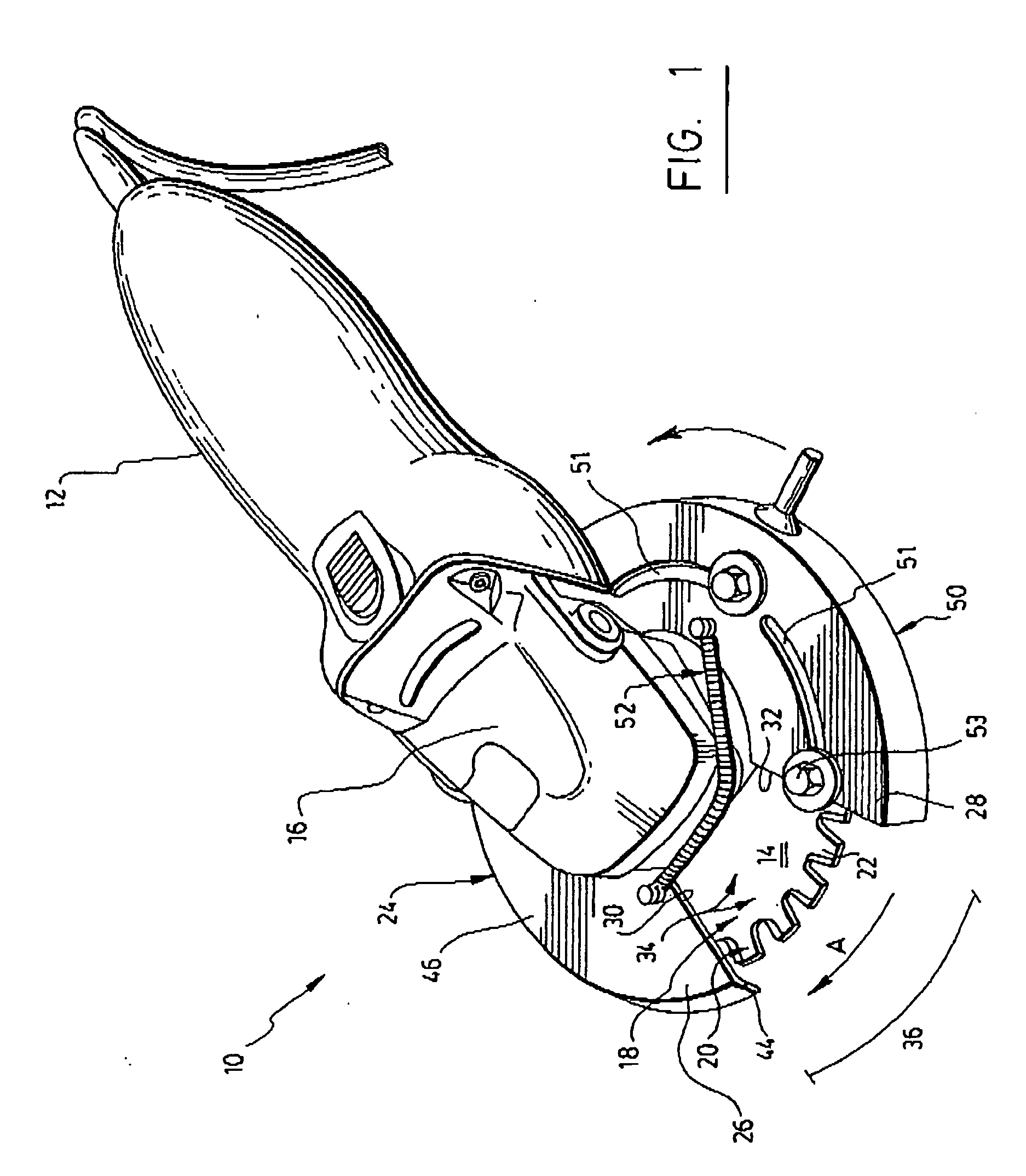
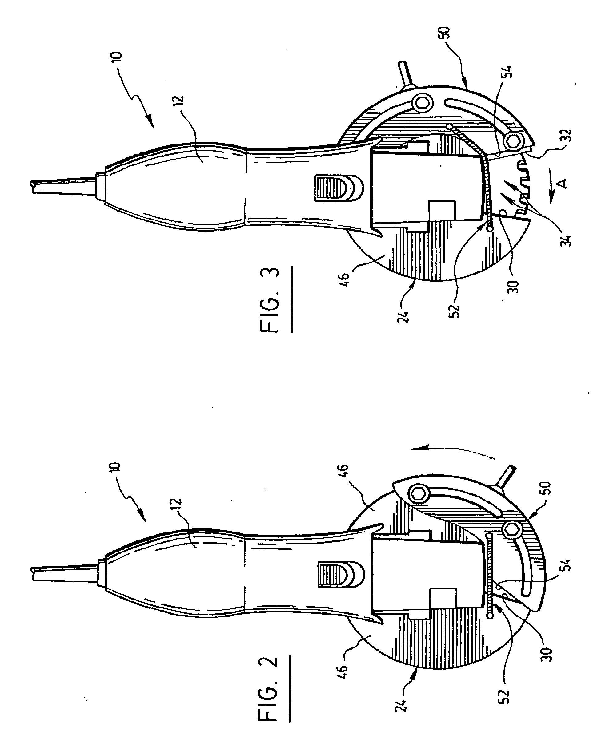
[0026]The first embodiment of the cutting device is illustrated in FIGS. 1 to 8, while the second embodiment is illustrated in FIG. 9. They share many common features, which will become apparent herebelow.

[0027]Referring to FIG. 1, the portable cutting device 10 has a main frame 12. To the frame 12, a circular blade 14 is drivably mounted. By drivably mounted it should be understood that the circular blade 14 is rotatably connected to the frame 12 so that a drive 16 may bring about the rotational movement of the blade. The speed of rotation is preferably about 2000 to 3000 RPMs, but could be modified depending on the operation of the drive and the properties of the object to be cut.

[0028]The circular blade 14 has a central portion (not sho...


PUM

PropertyMeasurementUnit
Widthaaaaaaaaaa
Areaaaaaaaaaaa
Dimensionaaaaaaaaaa

Abstract

The invention concerns a portable cutting device for cutting different sized objects. It includes a frame, a circular blade and a guiding guard mounted to the frame and around the blade. The guiding guard includes first and second projections extending beyond the periphery of the blade. Each projection has an edge being spaced-apart from and facing the other edge, and defining there-between a cutting area having a peripheral entrance. This enables an insertable object to be cut as it is guided into the blade along the edge facing the rotation direction, and a partially insertable object to be partially cut as it abuts against borders of the peripheral entrance. It also includes a protector removably mounted around the peripheral entrance to removably cover it. The invention also concerns a guard with adjustment elements movably mounted thereto to adjust the dimensions of the cutting area.

Description

FIELD OF THE INVENTION[0001]The present invention relates to the field of cutting devices, and more specifically to portable cutting devices for making precision guided cuts on objects of different sizes in metal, wood, or other materials.BACKGROUND OF THE INVENTION[0002]Numerous cutting devices are currently being used to cut materials. For example, to cut metal or polymer pipes or to cut aluminium siding, a variety of manual and automatic portable cutting devices are often employed.[0003]Tools having linear blades are used to cut an object by alternatively moving the blade back and forth on the object to be cut. In particular, portable cutting tools such as manual hacksaws, metal saws and other saws have been used to cut metallic or wooden objects. Such manual tools present numerous disadvantages, among which are loss of efficiency, exhausting the user and imprecision of cutting. Automatic tools having a linear blade have also been used in the prior art. These devices also present...

Claims


Application Information

Patent Timeline
IPC IPC(8): B27B5/00B27B5/29
CPCB23D45/003B27G19/04B23D45/16
Inventor SPINATO, DAVID
Owner SPINATO DAVID
Learn More