
Starter Arrangement for an Internal Combustion Engine

a technology for starting arrangements and internal combustion engines, which is applied in the direction of engine starters, couplings, auxilaries, etc., can solve the problems of inability to engage, new problems are introduced, and the starter-based system is low cost and scalable, so as to reduce the strain on the starter arrangement, reduce the thermal and mechanical strain on the one-way clutch, and increase the life of the one-way clutch

Inactive Publication Date: 2008-07-10
FORD GLOBAL TECH LLC
View PDF12 Cites 27 Cited by
  • Summary
  • Abstract
  • Description
  • Claims
  • Application Information

AI Technical Summary

Benefits of technology

[0007]According to an aspect of the present invention, the one-way clutch is arranged at an engine block side of a crankshaft oil seal enabling lubrication and cooling thereof by engine oil, whereby the thermal and mechanical strain on the one-way clutch will be reduced providing cooling and lubrication of the one-way clutch. An advantage of such an arrangement is that the life of the one-way clutch is increased.
[0008]Because the pinion gear is arranged in constant engagement with the corresponding crank gear of the crank wheel located between an engine block and a flywheel of the engine via a one-way clutch, strain on the starter arrangement is reduced, thereby prolonging its life.
[0009]According to another aspect of the present invention, the one-way clutch is arranged at an engine block side of a crankshaft oil seal enabling lubrication and cooling thereof by engine oil. Consequently, the thermal and mechanical strain on the one-way clutch is reduced by the provided lubrication and cooling of the one-way clutch.

Problems solved by technology

Starter-based systems are low cost and scalable to all sizes and kinds of powertrains but have two major drawbacks.
They cannot be engaged during engine ramp down (driver regret) and they are quite noisy due to engagement noise and cranking noise.
Although JP 2002 74337 addresses the noise and engagement problems by the ring gear engaging and always meshing with the pinion gear a new problem is introduced.
This is likely to put considerable strain on the one-way clutch of the starter arrangement.

Method used


Image

  • Starter Arrangement for an Internal Combustion Engine
  • Starter Arrangement for an Internal Combustion Engine
  • Starter Arrangement for an Internal Combustion Engine

Examples


Embodiment Construction

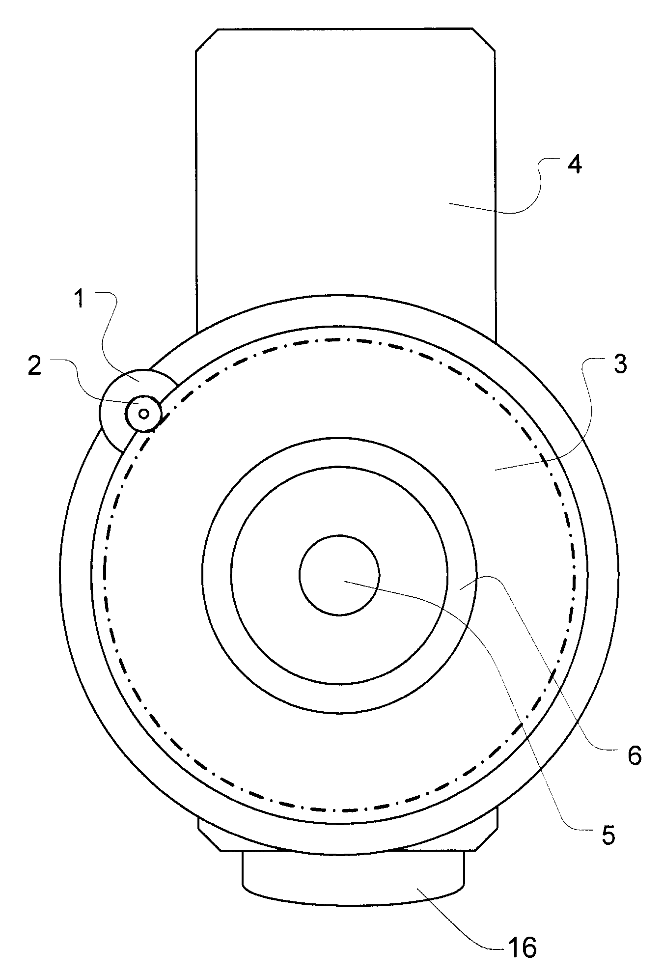
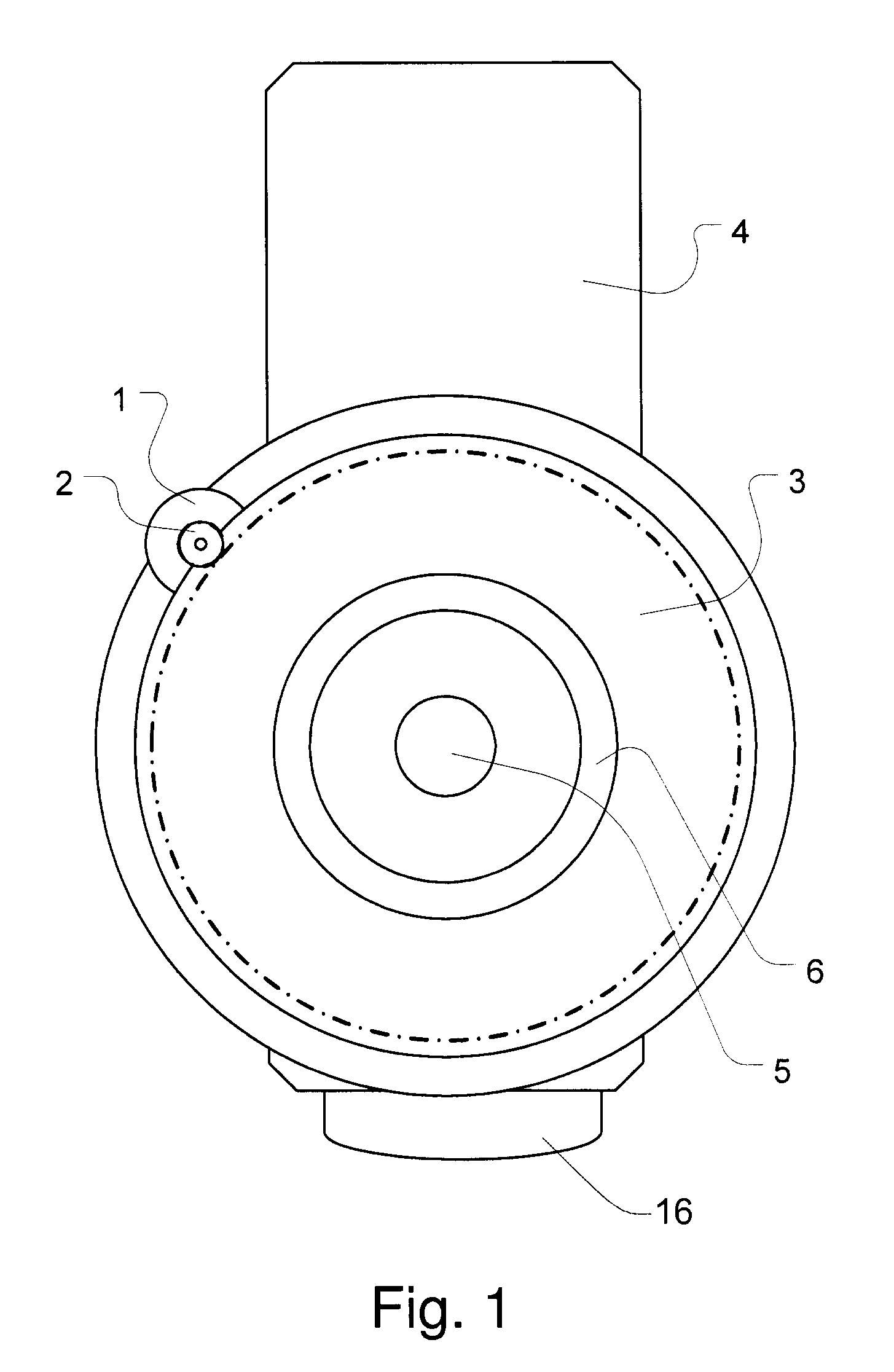
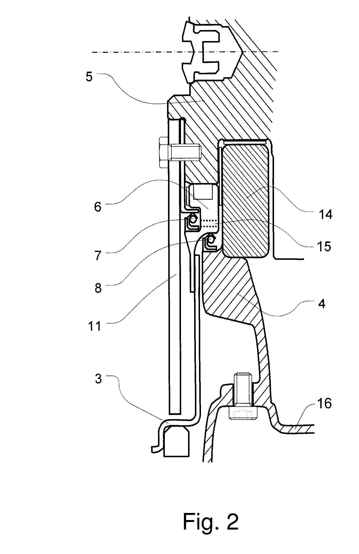
[0016]In one embodiment of the present invention shown schematically in FIG. 1, a starter arrangement for an internal combustion engine is shown. The starter arrangement comprises a starter motor 1, e.g. an electric starter motor, having a pinion gear 2 at an output shaft. The pinion gear 2 is arranged in constant engagement with a corresponding crank gear of a crank wheel 3 located between an engine block 4 and a flywheel 11 (as shown from a different perspective in FIG. 2) of the engine.

[0017]As shown in FIG. 2, crank wheel 3 is connected to a crankshaft 5 of the engine via a one-way clutch 6. The one-way clutch 6 is arranged at an engine block 4 side of a crankshaft oil seal 7 enabling lubrication and cooling thereof by engine oil.

[0018]In one embodiment, crank wheel 3 is a ring gear arranged to rotate with starter 1 during starting. Crank wheel 3 freewheels when the engine overruns starter 1. The one-way clutch 6 engages during starting and disengages during engine operation. Pr...


PUM


Abstract

The present invention relates to a starter arrangement for an internal combustion engine. The starter arrangement has a starter motor (1) having a pinion gear (2) at an output shaft. The pinion gear (2) is arranged in constant engagement with a corresponding crank gear of a crank wheel (3) located between an engine block (4) and a flywheel (11) of the engine. The crank wheel (3) is operatively connected to a crankshaft of the engine via a one-way clutch (6). The one-way clutch (6) is arranged at an engine block (4) side of a crankshaft oil seal (7) enabling lubrication and cooling thereof by an engine oil of the engine.

Description

TECHNICAL FIELD[0001]The present invention is related to a starter arrangement for an internal combustion engine adapted to facilitate start-stop operation.BACKGROUND OF THE INVENTION[0002]A start-stop or idle-stop operating mode is based on the concept of halting a vehicle combustion engine during vehicle standstill, e.g. when waiting for a traffic light to change from red to green. Such an arrangement may allow for substantial savings in fuel consumption. For mixed highway / rural and city driving savings of at least 2-4% are feasible and for city driving savings of up to 10% are feasible.[0003]Some previous attempts to provide such arrangements have been based on belt drives or have been starter based. Starter-based systems are low cost and scalable to all sizes and kinds of powertrains but have two major drawbacks. They cannot be engaged during engine ramp down (driver regret) and they are quite noisy due to engagement noise and cranking noise.[0004]One previous attempt at address...

Claims


Application Information

Patent Timeline
IPC IPC(8): F02N15/08F02N11/00F01M9/12F02F11/00
CPCF02N11/0814F02N15/022Y10T74/134F16D2300/06F16D41/00
Inventor FORSSELL, JONASGAST, PETER ULRIKSTENVALL, LARS JOHANALMHAGEN, PETTER
Owner FORD GLOBAL TECH LLC
Learn More