
Intelligent boom control device

a boom control and intelligent technology, applied in the field of intelligent boom control devices, can solve the problems of complex operation, obvious drawbacks of the intelligent boom control device described above, and the experienced operator can hardly keep the height of the boom end b, so as to achieve the effect of straight line control

Inactive Publication Date: 2008-07-03
SANY HEAVY IND CO LTD (CN)
View PDF7 Cites 44 Cited by
  • Summary
  • Abstract
  • Description
  • Claims
  • Application Information

AI Technical Summary

Benefits of technology

[0021]The present invention provides an intelligent boom control device which can move a boom end from one position to another along a straight line track and therefore satisfy the requirement of the construction where the movement track of the boom end must be a straight line.
[0057]According to the control device provided by the present invention, it is possible for an operator to easily accomplish the straight line control of the movement track of the boom end, and is especially suitable to occasions requiring the movement track of the boom end to be straight line such as concrete pump truck and the like.

Problems solved by technology

This embodiment does not require a boom measuring and sensing system as well as a coordinate transformation system supported by computer, however, it cause complicated operation.
However, to accomplish this operation quickly, even an experienced operator can hardly keep the height of the boom end 20 during the process of movement.
However, the intelligent boom control device described above still has obvious drawback.
However, in the case of cement placing and the like where control requirement for movement track of the boom end N is relatively high, the above movement track can't satisfy the operating requirement.

Method used


Image

  • Intelligent boom control device
  • Intelligent boom control device
  • Intelligent boom control device

Examples


Embodiment Construction

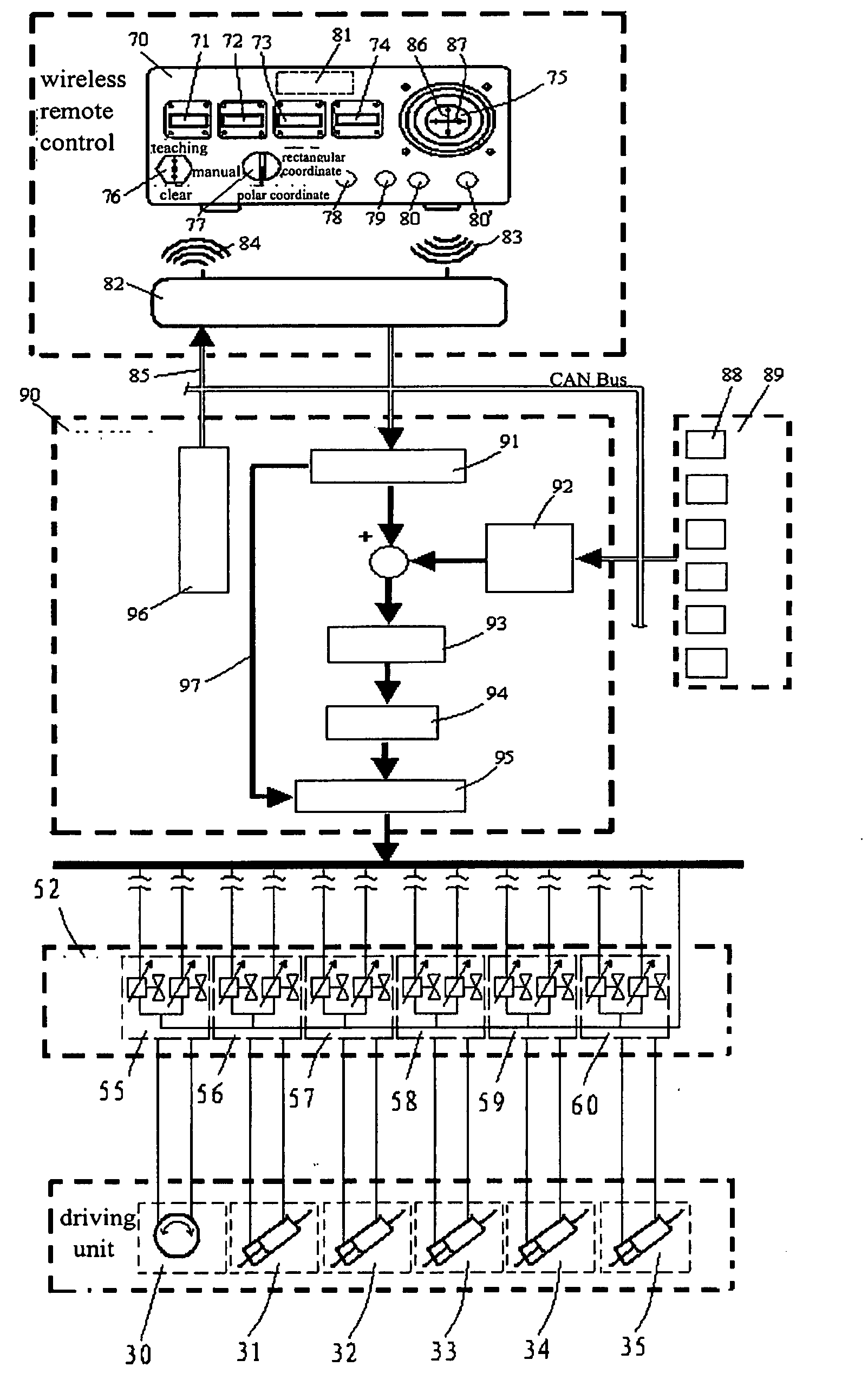
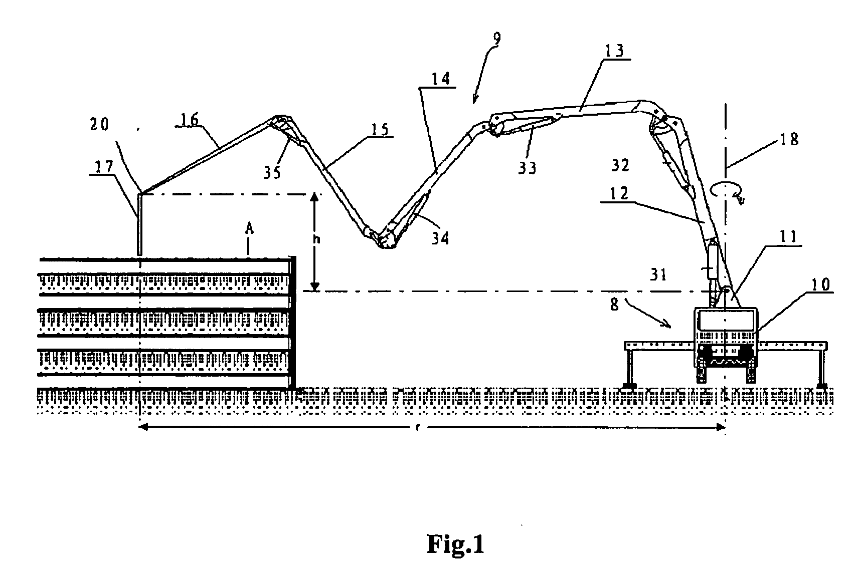
[0072]Hereafter, an embodiment of the intelligent boom control device provided in the invention will be described referring the boom structure of the concrete pump truck shown in FIG. 1. The boom structure of the concrete pump truck has been described in the background art, and will not be described again herein. Because the key problem solved by the present invention is the control of a boom moving in a horizontal plane, the following description will mainly focus on the movement control of the boom in a horizontal plane. Control of the boom lifting and lowering in vertical direction will not be described in detail herein because it is simpler than the movement control in a horizontal plane.

[0073]FIG. 4 shows a principle block diagram of an intelligent boom control device according to the first embodiment of the present invention.

[0074]As shown in FIG. 4, this intelligent boom control device includes a remote controller 70, a receiver 82 fixed to a concrete pump truck, an angle mea...


PUM


Abstract

The present invention discloses an intelligent boom control device including: a control unit and an angle measurement unit, the control unit calculating the boom position information based on measured value of angles, whereby adjusting the control of various actuators; the device further including: a remote controller which transmits control commands in the form of wireless remote control and can provide movement control commands including X axis component, Y axis component and Z axis component used in a rectangular coordinate system; a rectangular coordinate system being defined in a space, X axis, Y axis and Z axis of this rectangular coordinate system corresponding to each of the coordinate axis components in the movement control command of the remote controller; when the remote controller transmits a movement control command, the control unit determining the movement direction of the boom end in a plane according to the X axis component and Y axis component of the received movement control command, and decomposing the movement into movement of each boom section and the rotary platform so that the boom end moves to the direction indicated by the movement control command. According to the device provided by the present invention, it is possible for an operator to easily accomplish the straight line control of the movement track of the boom end.

Description

CROSS-REFERENCES TO RELATED APPLICATIONS[0001]This application claims priority to Chinese Patent Application No. 200610156416.8, filed Dec. 31, 2006, commonly assigned, incorporated by reference herein for all purposes.BACKGROUND OF THE INVENTION[0002]The present invention relates to a boom control device. In particular, the invention relates to an intelligent boom control device.[0003]Various construction vehicles with boom are widely used. The boom is a device including at least three boom sections hinged by horizontal joint shafts. Each boom section can rotate a considerable angle around the joint shafts. Meanwhile, the whole boom is fixed to a machine frame by rotary platform, which can bring the whole boom to rotate around the upright axis vertical to the horizontal plane for 360 degree. A typical application of this boom is to act as construction apparatus, for example to move objects from one spot to another and hang up them. At present, such boom devices are widely applied t...

Claims


Application Information

Patent Timeline
Patent Type & Authority Applications(United States)
IPC IPC(8): G06F19/00
CPCB66C13/40E04G21/04B66C23/005B66C13/46E04G21/0436E04G21/0463B66F11/00B66C13/18E02F9/20
Inventor TANG, XIUJUNSHI, PEIKELI, SHENGHUAZHOU, SONGYUN
Owner SANY HEAVY IND CO LTD (CN)
Learn More