Method for routing a robotic apparatus to a service station and robotic apparatus service system using thereof

Inactive Publication Date: 2008-07-03
IND TECH RES INST
View PDF15 Cites 115 Cited by
  • Summary
  • Abstract
  • Description
  • Claims
  • Application Information

AI Technical Summary

Benefits of technology

[0007]It is an object of the present invention to provide a method for routing a robotic apparatus to a service station and a robotic apparatus service system using the same, in which by the detection of a most intense communication signal emitted from the service station, a moving direction can be determined for guiding the robotic apparatus back to the service station in a shortest way by rectilinear motion that is not only efficient, but also time-saving.
[0009]It is yet another object of the invention to provide a method for routing a robotic apparatus to a service station and a robotic apparatus service system using the same, in which by arranging a signal emitter array in a service station for increasing signal coverage, a robotic apparatus is able to detect and receive a communication signal emitted from the service station while operating at any location of a specified working area so as to utilize the communication signal as guidance for routing the robotic apparatus to the service station, so that less time is waste in the searching for the communication signal and thus the reliability as well as accuracy for routing the robotic apparatus to the service station are enhanced.
[0010]It is further another object of the invention to provide a method for routing a robotic apparatus to a service station and a robotic apparatus service system using the same, in which by the utilization of directional units to control the signal receiving range of a robotic apparatus, it is able to direct the robotic apparatus to move efficiently toward a service station in a rectilineal motion.

Problems solved by technology

However, in actual practices, when the robotic vacuum cleaner 101 is situated in a complicated working environment, or even when the robotic vacuum cleaner 101 operating in the wall-following mode accidentally enters sections out of the coverage of the plural charging devices 10 as the wall-following mode can be misleading, the success rate of guiding the robotic vacuum cleaner 101 to establish contact with any charging device 10 can be very slim so that the aforesaid battery charging method is inefficiency and untrustworthy.
Thus, in most case, it would take the robotic device 111 quite some times to search an infrared light beam for guiding itself back to the base station 11 for charging, so that the reliability of the aforesaid method is adversely affected and questioned.
Therefore, in most case, it would take the robotic device quite some times to search an infrared light beam for guiding itself back to the base station for charging, so that the reliability of the aforesaid method is adversely affected and questioned.
In addition, the arranging of two infrared sensors will cause the manufacturing cost of the robotic device to increase and thus adversely affect its commercial competitiveness.

Method used


Image

  • Method for routing a robotic apparatus to a service station and robotic apparatus service system using thereof
  • Method for routing a robotic apparatus to a service station and robotic apparatus service system using thereof
  • Method for routing a robotic apparatus to a service station and robotic apparatus service system using thereof

Examples


first embodiment

[0032]Please refer to FIG. 2A, which is a flow chart illustrating steps of a method for routing a robotic apparatus to a service station according to the invention. The flow of the method starts from step 20. At step 20, a robotic apparatus is enabled to search for a communication signal emitted from a service station, whereas the robotic apparatus is able to search for a communication signal by a manner selected from the group consisting of: searching the communication signal dynamically while the robotic apparatus is on the move, directing the robotic apparatus to rotate without moving while searching the communication signal, and the combination thereof; and then the flow proceeds to step 21.

[0033]At step 21, the robotic apparatus is enabled to rotate for locating a moving direction pointing to the communication signal of maximum intensity, as that indicated in FIG. 2B, and then as soon as the moving direction pointing to the communication signal of maximum intensity is located, ...

second embodiment

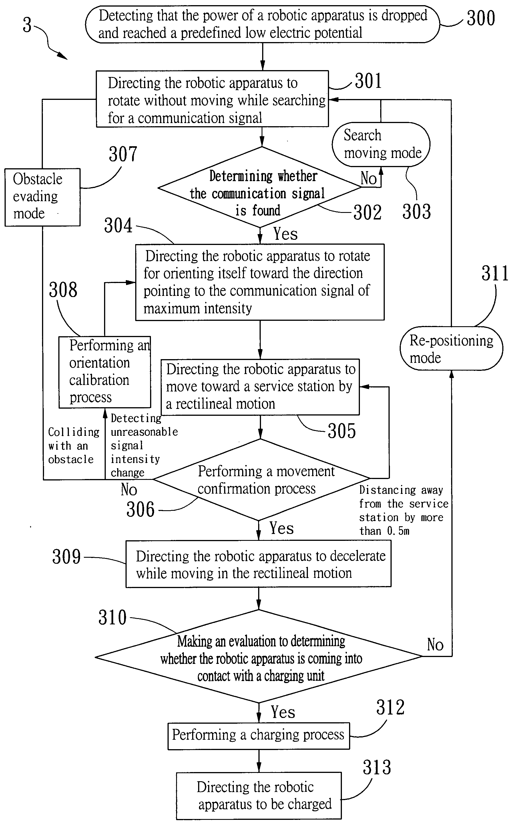
[0037]For clarity, the aforesaid routing method is applied for guiding a robotic vacuum cleaner back to a charging station for charging. Please refer to FIG. 3A, which is a flow chart illustrating steps of a method for routing a robotic vacuum cleaner to a service station according to the invention. The flow starts from step 300. At step 300, the power of a robotic vacuum cleaner is detected and if it had dropped and reached a predefined low electric potential, the flow will proceed to step 301. At step 301, the robotic vacuum cleaner is directed to rotate without moving while searching for a communication signal; and then the flow proceeds to step 302. At step 302, an evaluation is being made for determining whether the communication signal is found; if so, the flow proceeds to step 304; otherwise, the flow proceeds to step 303. At step 303, the robotic vacuum cleaner is enabled to enter a search moving mode that the robotic vacuum cleaner is kept searching for the communication si...


PUM


Abstract

A method for routing a robotic apparatus to a service station and robotic apparatus service system using thereof are disclosed in the present invention, wherein the system comprises at least one service station and a robotic apparatus. The service station is capable of providing charging service and has a signal emitter array which functions to emit communication signals for guiding the robotic apparatus back to the service station. The robotic apparatus has a signal receiver for searching and detecting the communication signal emitted from the service station and determines the moving direction according to the intensity of the communication signal received by the signal receiver so as to arrive at the service station smoothly through the method disclosed in the present invention. Once the robotic apparatus arrives at the service station, the service station may provide service such as charging to the robotic apparatus while the robotic apparatus may standby to wait for the accomplishment of charging. By means of the method and system provided in the present invention, the robotic apparatus may route to the service station in a shortest way by rectilineal motion and contact to the service station to receive the service in arbitrary angle.

Description

FIELD OF THE INVENTION[0001]The present invention relates to a path guidance method and system, and more particularly, to a robotic apparatus service method and system capable of enabling a robotic apparatus to received a radio wave guidance signal issued from a signal emitter array of a service station by at least a signal receiver arranged thereon, and thereby, guiding the robotic apparatus to move toward the service station to be served by the service station.BACKGROUND OF THE INVENTION[0002]Conventionally, a robotic apparatus can be defined as an automatically controlled, mobile device which is capable of being programmed to execute at least a task within a specific working area. Usually, one such robotic apparatus, e.g. a mobile robot, is a self-reliance device that is moving and operating by a built-in power source, whereas the built-in power source can be a rechargeable battery. Thus, in order to keep a mobile robot operational, it must return to a service station for chargin...

Claims


Application Information

Patent Timeline
IPC IPC(8): G06F19/00
CPCG05D1/0225G05D2201/0215G05D1/0234
Inventor LEE, SHIH-PINGCHUNG, YU-LIANGCHEN, LONG-DERYU, HUNG-HSIULIAO, CHING-CHI
Owner IND TECH RES INST
Why Eureka
Try Eureka