
Method and apparatus for handoff in a wireless network

Active Publication Date: 2008-07-03
RPX CORP
View PDF12 Cites 11 Cited by
  • Summary
  • Abstract
  • Description
  • Claims
  • Application Information

AI Technical Summary

Problems solved by technology

As described above, a problem occurs in the prior art when a network controller receives a pilot signal identification from a mobile station, where the received pilot signal identification is not present on a neighbor list of the mobile station.

Method used


Image

  • Method and apparatus for handoff in a wireless network
  • Method and apparatus for handoff in a wireless network
  • Method and apparatus for handoff in a wireless network

Examples


Embodiment Construction

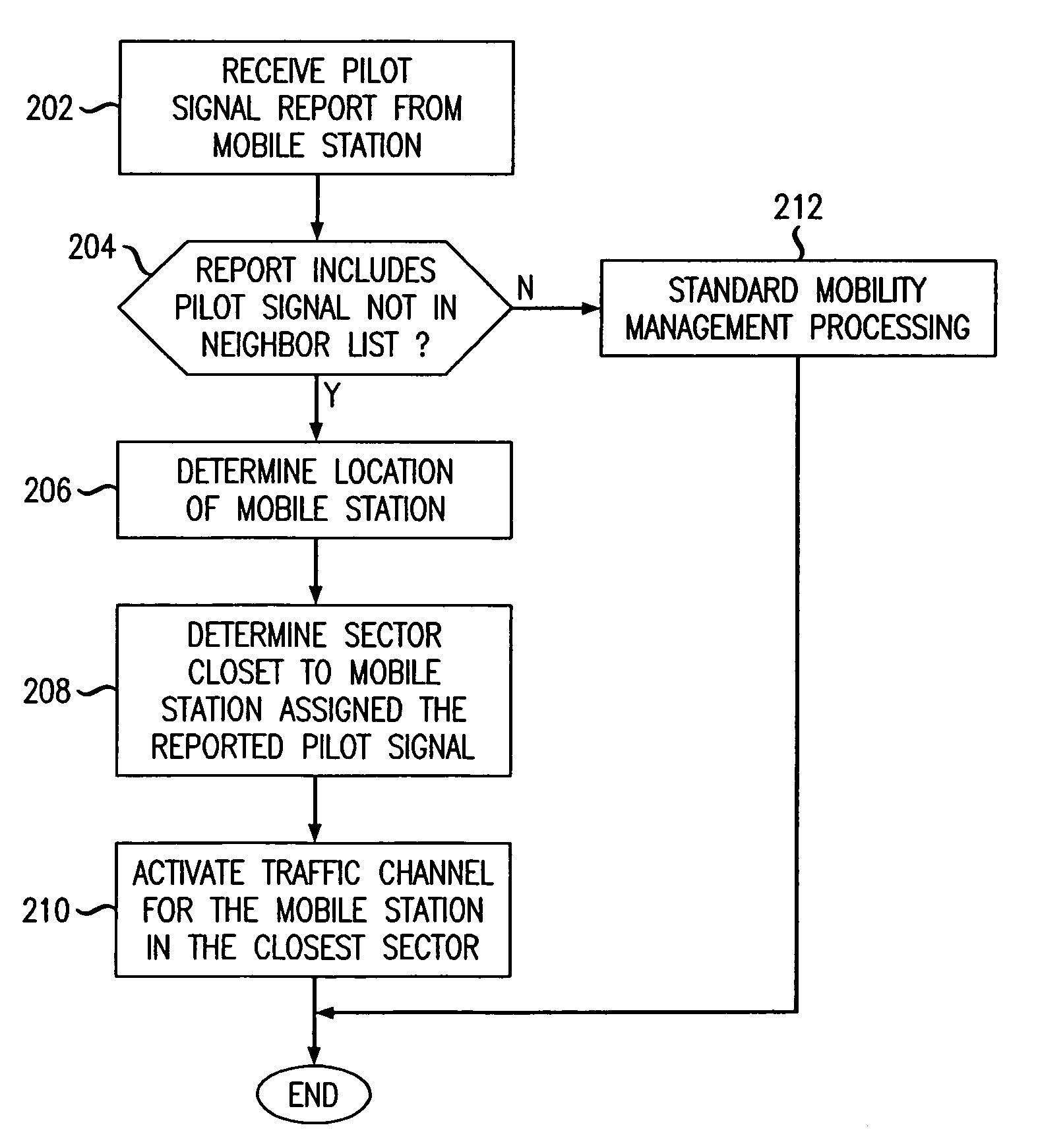
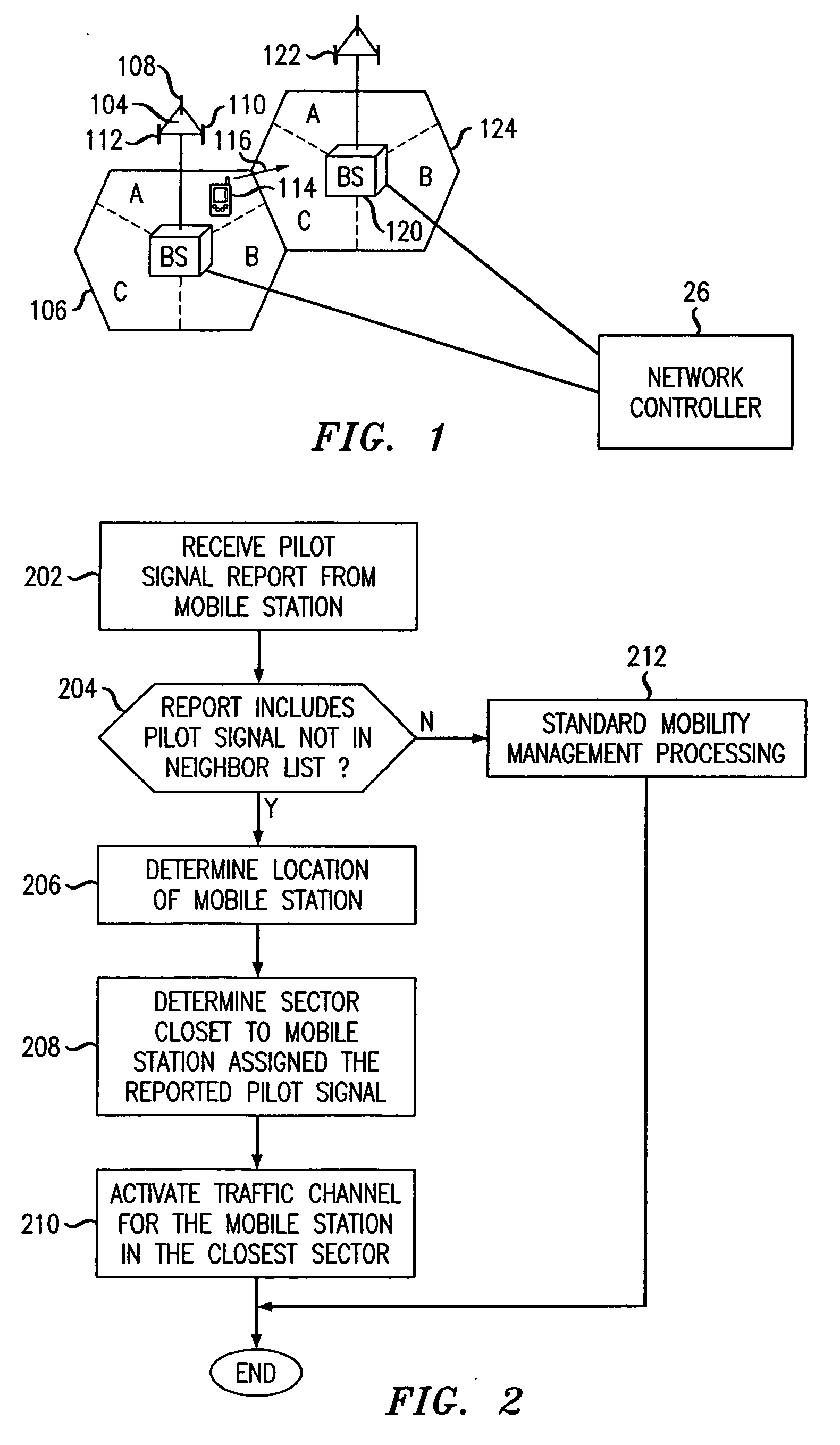
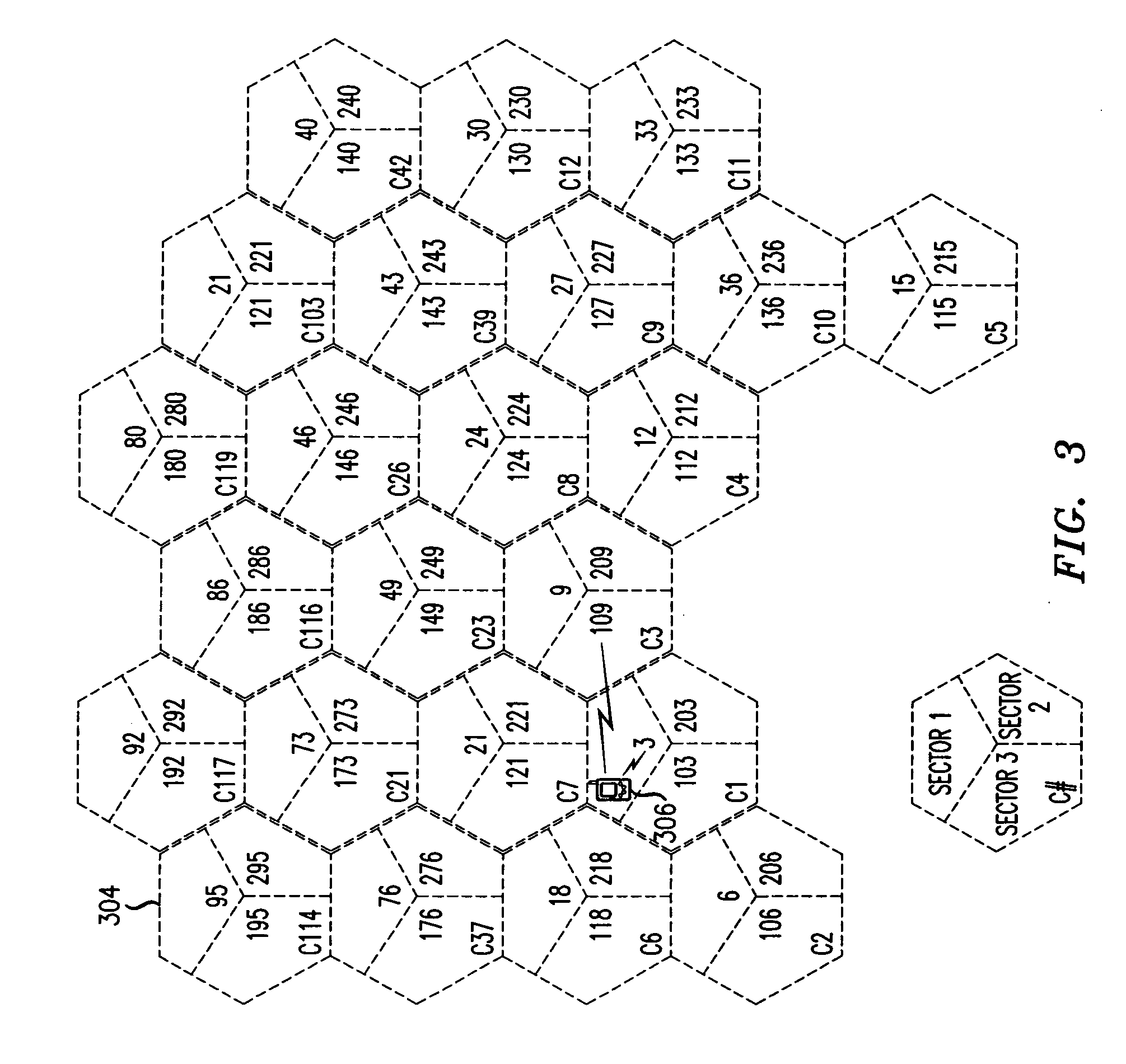
[0022]In accordance with an aspect of the invention, when a mobile terminal detects a pilot signal that is not in any of its neighbor lists, the system activates a traffic channel in the sector associated with the pilot signal that is the most likely candidate for a handoff. In one embodiment, the sector associated with the pilot signal and closest to the mobile terminal is identified as the most likely candidate. In other embodiments, the sector antenna angle (azimuth) and gain pattern information may be used to determine the most likely candidate, in addition to the distances. Full propagation predictions, which include terrain elevation, clutter morphology and other parameters, in addition to distances and sector antenna information, could also be used, as available from various prediction tools for RF propagation.

[0023]FIG. 2 is a flowchart showing the steps performed by a CDMA network controller, for example network controller 26 of FIG. 1, in accordance with one embodiment of ...


PUM


Abstract

In response to a determination that a received pilot signal identification is not present in a current neighbor list of a mobile station, a network controller identifies one of a plurality of sectors associated with the missing pilot signal identification that is a most likely handoff candidate. In one embodiment, the most likely handoff candidate is determined as the sector that is closest to the mobile station. When the most likely candidate is identified, a handoff may be initiated between the mobile station and the identified sector. The handoff may be accomplished by activating a traffic channel for the mobile station in the identified sector.

Description

BACKGROUND OF THE INVENTION[0001]The present invention relates generally to wireless networks, and more particularly to handoff in wireless networks.[0002]Code Division Multiple Access (CDMA) wireless networks are well known in the art for providing wireless voice and data services to mobile stations within the network's service area. CDMA is a spread spectrum technology, in that multiple users share the same broadband frequency range. Individual spreading codes, assigned to each of the multiple users, allows the signals for a particular user to be extracted from the transmitted signal. CDMA technology is well known in the art and will not be described in detail herein.[0003]Mobile stations within a CDMA network communicate via base stations. Each base station serves a geographic area, often referred to as a cell. Each cell may be further divided into sectors, whereby each sector in a cell is served by one or more directional antennas associated with the base station serving the cel...

Claims


Application Information

Patent Timeline
Patent Type & Authority Applications(United States)
IPC IPC(8): H04Q7/20H04W36/18H04W36/30
CPCH04W36/30H04W36/18H04W36/0061
Inventor JOVANOVIC, VLADAN
Owner RPX CORP
Learn More