Helicopter blade mandrel

a technology for helicopters and mandrels, which is applied in the field of helicopter rotor blades, can solve the problems of difficult to remove molds or mandrels after spar cure, difficult to find foam or other materials that have the structural strength to maintain critical spar dimensions, and complex set of aerodynamic forces on the rotor blades. achieve the effect of easy removal of spars

Active Publication Date: 2008-07-03
HEXCEL
View PDF15 Cites 22 Cited by
  • Summary
  • Abstract
  • Description
  • Claims
  • Application Information

AI Technical Summary

Benefits of technology

[0011]In accordance with the present invention, methods and apparatus are provided for making a rotor blade spar from composite material wherein a multi-component mandrel is used to form the composite spar. The mandrel is made using a number of components, which are assembled to provide a structure that is sufficiently strong to maintain the spar shape during pre-cure lay up, compaction and curing of the composite material. The multiple components used to form the mandrel can be separated from each other and easily removed from the spar either before or after curing of the composite material. The mandrel components can then be re-assembled and re-used to form additional composite spars.
[0016]The present invention also covers methods for making the multi-component mandrel as well as the methods for molding composite rotor blade spars using the multi-component mandrel and the resulting rotor blade spar. The multi-component mandrel of the present invention provides a number of advantages over existing methods for making composite rotor blades. These advantages include the ability to withstand the forces applied to the mandrel during fabrication of the composite blade in order to avoid any undesirable variations in blade shape. In addition, the mandrel can be used to form complex spar shapes including spars with varying degrees of twist and changes in elliptical cross-sectional geometry. A further advantage is that the mandrel can be re-assembled and used repeatedly.

Problems solved by technology

The rotor blades are subjected to a complex set of rather extreme aerodynamic forces that vary continually during flight.
A problem associated with making composite spars revolves around what to do with the mold or mandrel once the spar has been formed.
The length of the mold and the variations in elliptical cross-section of the spar, as well as any twist in the spar, make it very difficult to remove the mold or mandrel after the spar has cured.
Although foam molds have been used successfully in fabricating composite spars for rotor blades, it is many times difficult to find a foam or other material that has the needed structural strength to maintain critical spar dimensions during formation of the spar, while at the same time being able to deteriorate relatively rapidly during cure.
In addition, the mold can only be used once, which adds considerably to the cost of spar fabrication.

Method used


Image

  • Helicopter blade mandrel
  • Helicopter blade mandrel
  • Helicopter blade mandrel

Examples


Embodiment Construction

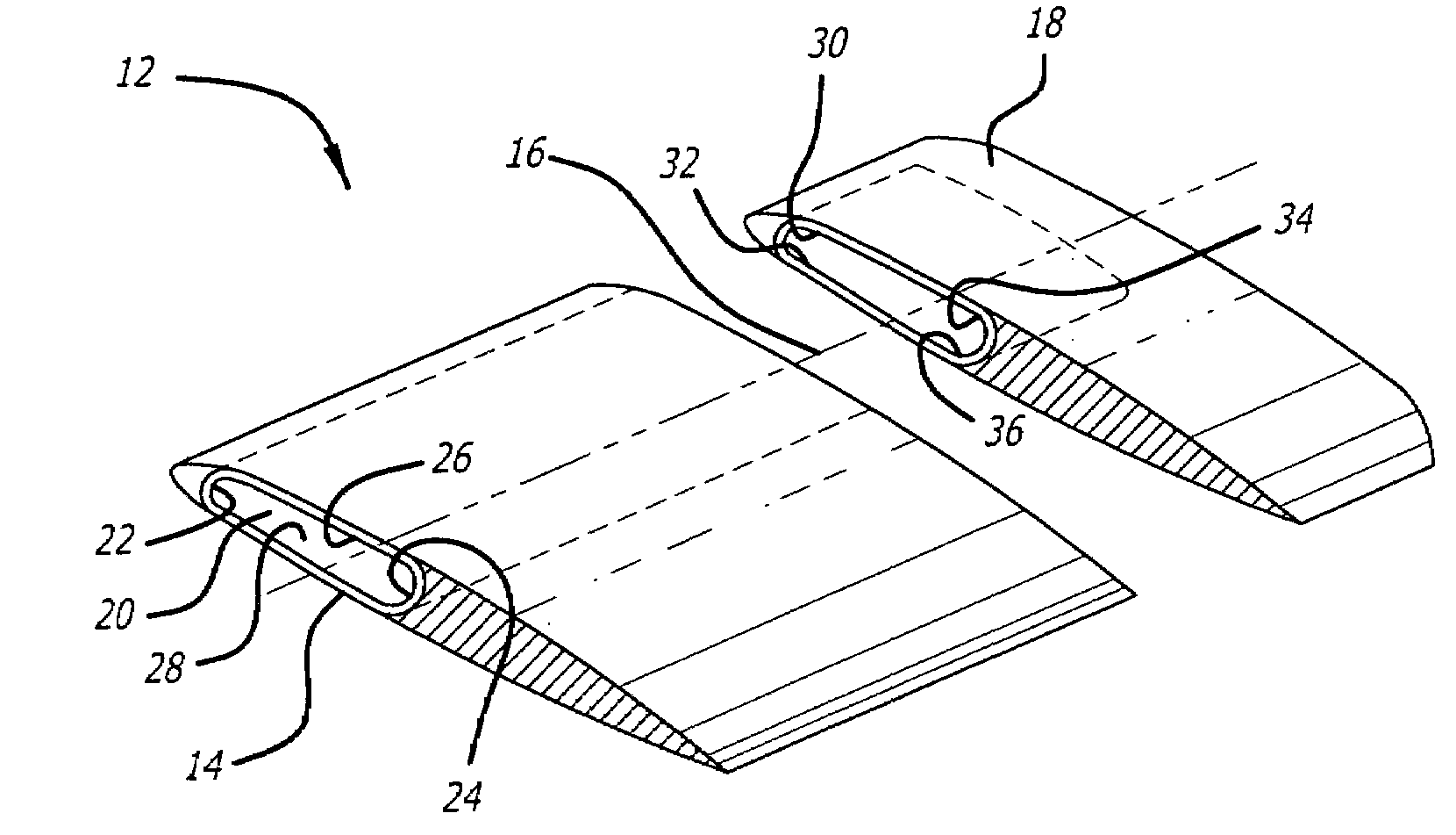
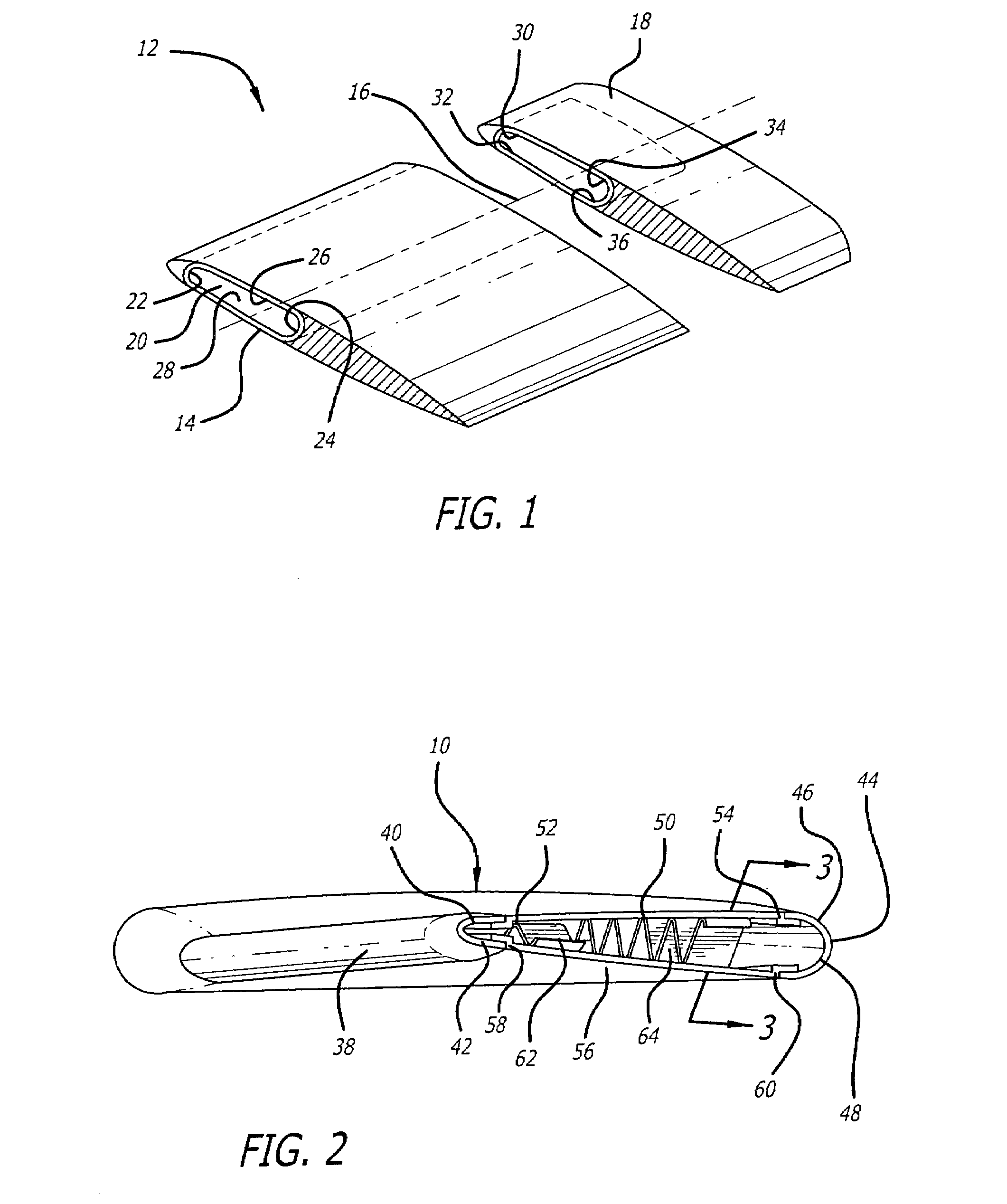
[0023]A preferred exemplary multi-component mandrel in accordance with the present invention for use in molding a helicopter rotor blade from composite material is shown generally at 10 in FIG. 2. An exemplary helicopter rotor blade that can be molded utilizing the mandrel 10 is shown in a simplified form in FIG. 1 at 12. The rotor blade 12 includes a spar 14 that extends parallel to the longitudinal axis 16 of the rotor blade 12. The spar 14 typically extends from the root of the rotor blade (not shown) to the tip 18. The spar 14 is a tubular structure that has an elliptically shaped cross-section as shown in FIG. 1. The spar 14 includes a number of interior surfaces that are formed by the mandrel 10. These interior spar surfaces define the spar cavity 20.

[0024]Referring to FIG. 1, the spar interior surfaces are composed of a leading edge surface 22, trailing edge surface 24, an upper surface 26 and a lower surface 28. The leading edge surface 22 includes an upper leading edge port...


PUM

PropertyMeasurementUnit
Forceaaaaaaaaaa
Distanceaaaaaaaaaa
Resilienceaaaaaaaaaa

Abstract

Methods and apparatus are provided for making a rotor blade spar from composite material wherein a multi-component mandrel is used to form the composite spar. The mandrel is made using a number of components, which are assembled to provide a structure that is sufficiently strong to maintain the spar shape during pre-cure lay up, compaction and curing of the composite material. The multiple components used to form the mandrel can be separated from each other and easily removed from the spar either before or after curing of the composite material. The mandrel components can then be re-assembled and re-used to form additional composite spars.

Description

BACKGROUND OF THE INVENTION[0001]1. Field of the Invention[0002]The present invention relates generally to helicopter rotor blades that are made from composite materials. More particularly, the present invention is directed to the processes and apparatus that are used in the manufacture of such composite rotor blades.[0003]2. Description of Related Art[0004]Rotor blades are a critical component of every helicopter. The rotor blades are subjected to a complex set of rather extreme aerodynamic forces that vary continually during flight. The rotor blades function as rotating airfoils or wings that are shaped to provide the aerodynamic lift required for a given aircraft. Rotor blades typically include a spar that extends from the root of the rotor blade to its tip. The spar is a major structural element of the rotor blade that provides the blade with the structural strength needed to carry high operational loads.[0005]The typical rotor blade spar is a long tubular structure around which...

Claims


Application Information

Patent Timeline
IPC IPC(8): B29D22/00B29C33/42F01D5/14
CPCB29C33/485B29D22/00Y10T156/1002B29L2031/082B29D99/0028
Inventor CALLIS, RICHARD A.WHITE, JOENEWKIRK, SCOTTWHITE, JANE
Owner HEXCEL
Why Eureka
Try Eureka