
Implantable medical device comprising magnetic field detector

a magnetic field detector and medical device technology, applied in the field of implantable medical devices, can solve the problem that the reed switch cannot distinguish between a magnetic field of 2 mt or 1.5

Inactive Publication Date: 2008-06-26
BIOTRONIX CRM PATENT AG
View PDF12 Cites 102 Cited by
  • Summary
  • Abstract
  • Description
  • Claims
  • Application Information

AI Technical Summary

Benefits of technology

[0008]It is an object of the invention to provide an implantable medical device that has a sensor that is able to differentiate between low-level and very high-level magnetic fields, as that would make it possible to automatically place the device into a patient safe “MRI mode” if the presence of an MRI magnetic field were detected.

Problems solved by technology

MRI is a diagnostic tool that has become increasingly popular, and is typically contraindicated for pacemaker and ICD patients due to possible mechanical forces, heating of leads, permanent damage to the electronic circuit or inappropriate therapy (e.g. loss of sensing or pacing at the UTR).
However, a reed switch is unable to differentiate between a magnetic field of 2 mT or 1.5 T.

Method used


Image

  • Implantable medical device comprising magnetic field detector
  • Implantable medical device comprising magnetic field detector
  • Implantable medical device comprising magnetic field detector

Examples


Embodiment Construction

[0035]The following description is of the best mode presently contemplated for carrying out the invention. This description is not to be taken in a limiting sense, but is made merely for the purpose of describing the general principles of the invention. The scope of the invention should be determined with reference to the claims.

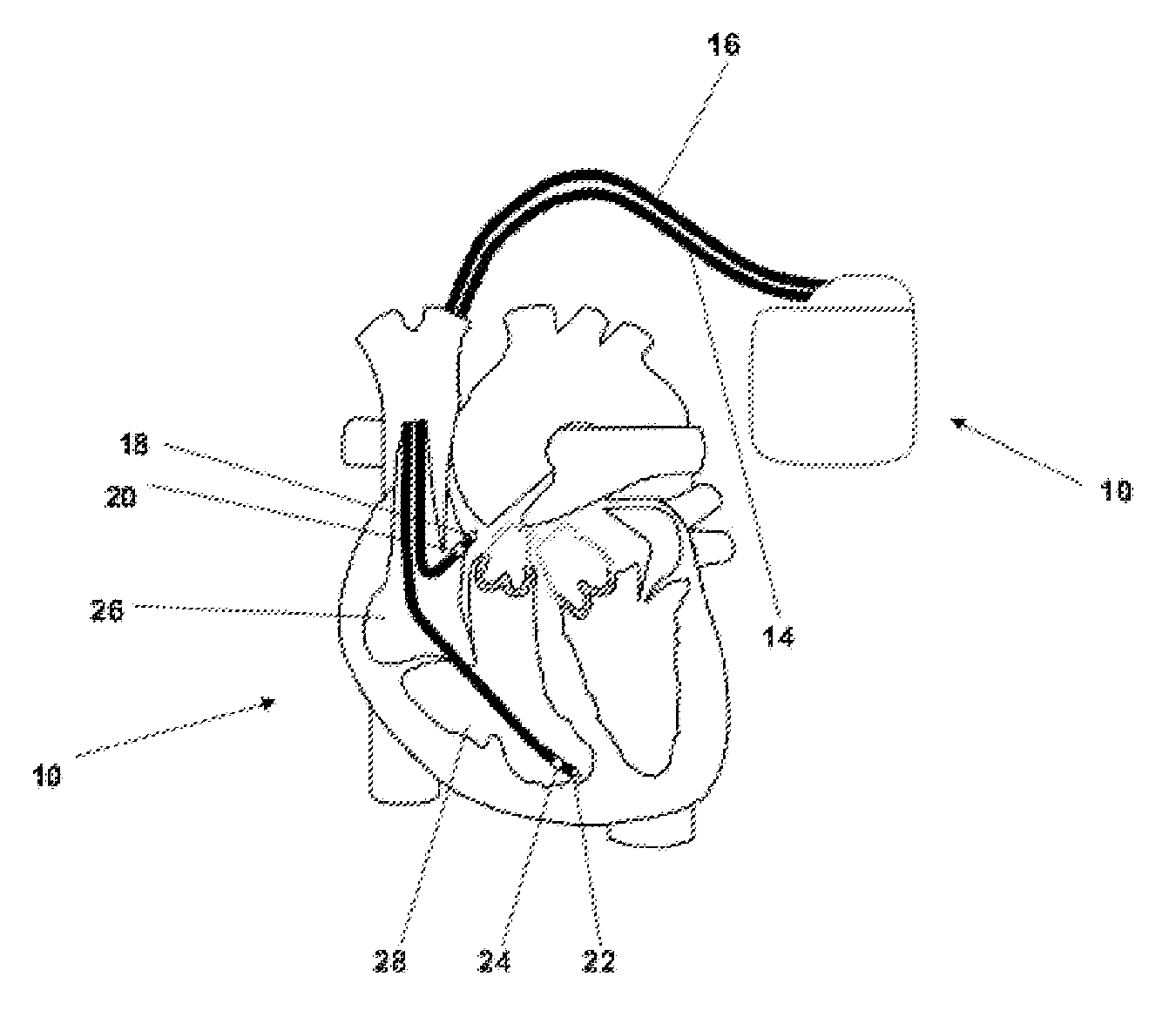
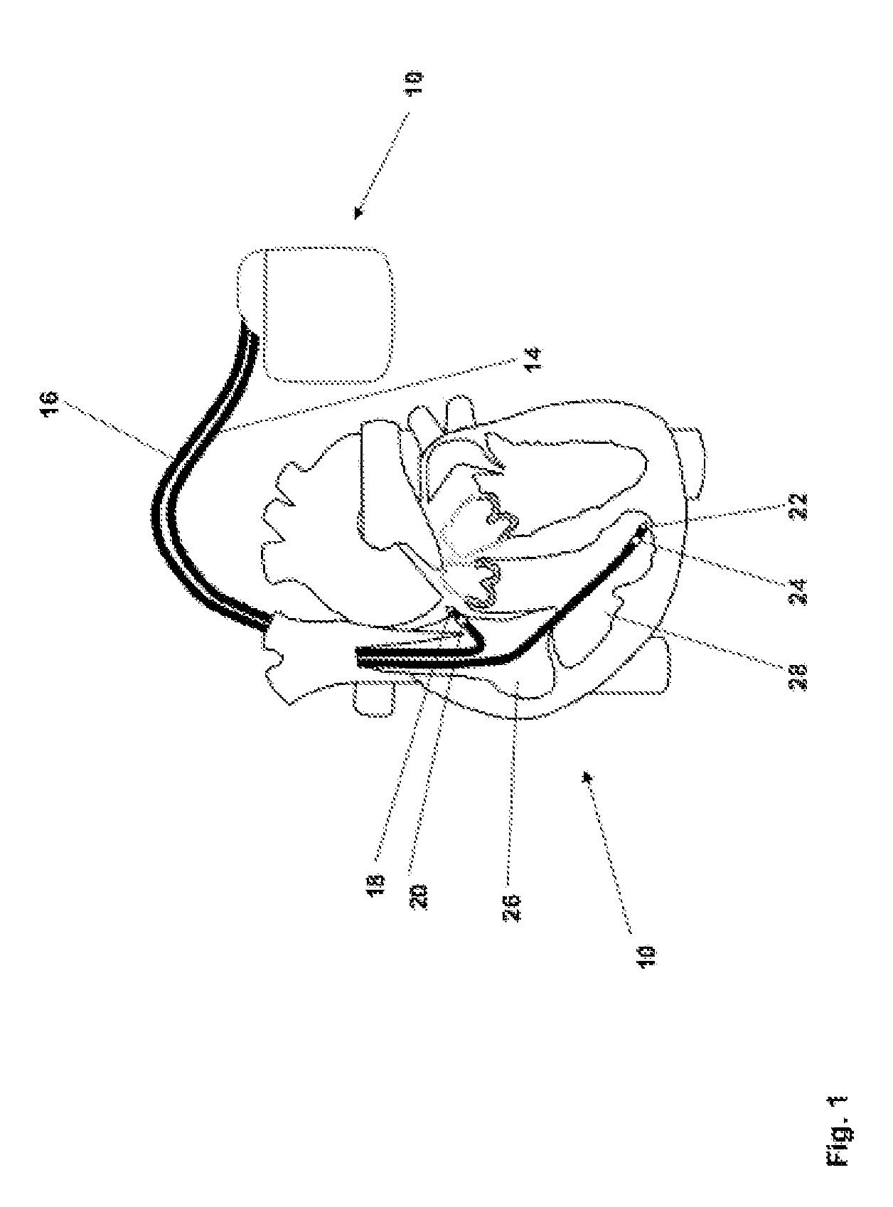
[0036]In FIG. 1 a dual chamber pacemaker 10 as heart stimulator connected to pacing / sensing leads placed in a heart 12 is illustrated. The pacemaker 10 is electrically coupled to heart 12 by way of leads 14 and 16. Lead 14 has a pair of right atrial electrodes 18 and 20 that are in contact with the right atria 26 of the heart 12. Lead 16 has a pair of electrodes 22 and 24 that are in contact with the right ventricle 28 of heart 12. Electrodes 18 and 22 are tip-electrodes at the very distal end of leads 14 and 16, respectively. Electrode 18 is a right atrial tip electrode RA-Tip and electrode 22 is a right ventricular tip electrode 22. Electrodes 20 and 24 ar...


PUM


Abstract

An implantable medical device comprises an electronic control unit and a magnetic resonance imaging magnetic field detector that is connected to the control unit. The magnetic resonance imaging magnetic field detector is adapted to generate a signal being characteristic for a magnetic field as used for magnetic resonance imaging (MRI) and the control unit is adapted to positively recognize a presence of a magnetic field as used for magnetic resonance imaging (MRI) and to cause the implantable medical device to enter an MRI-safe mode of operation.

Description

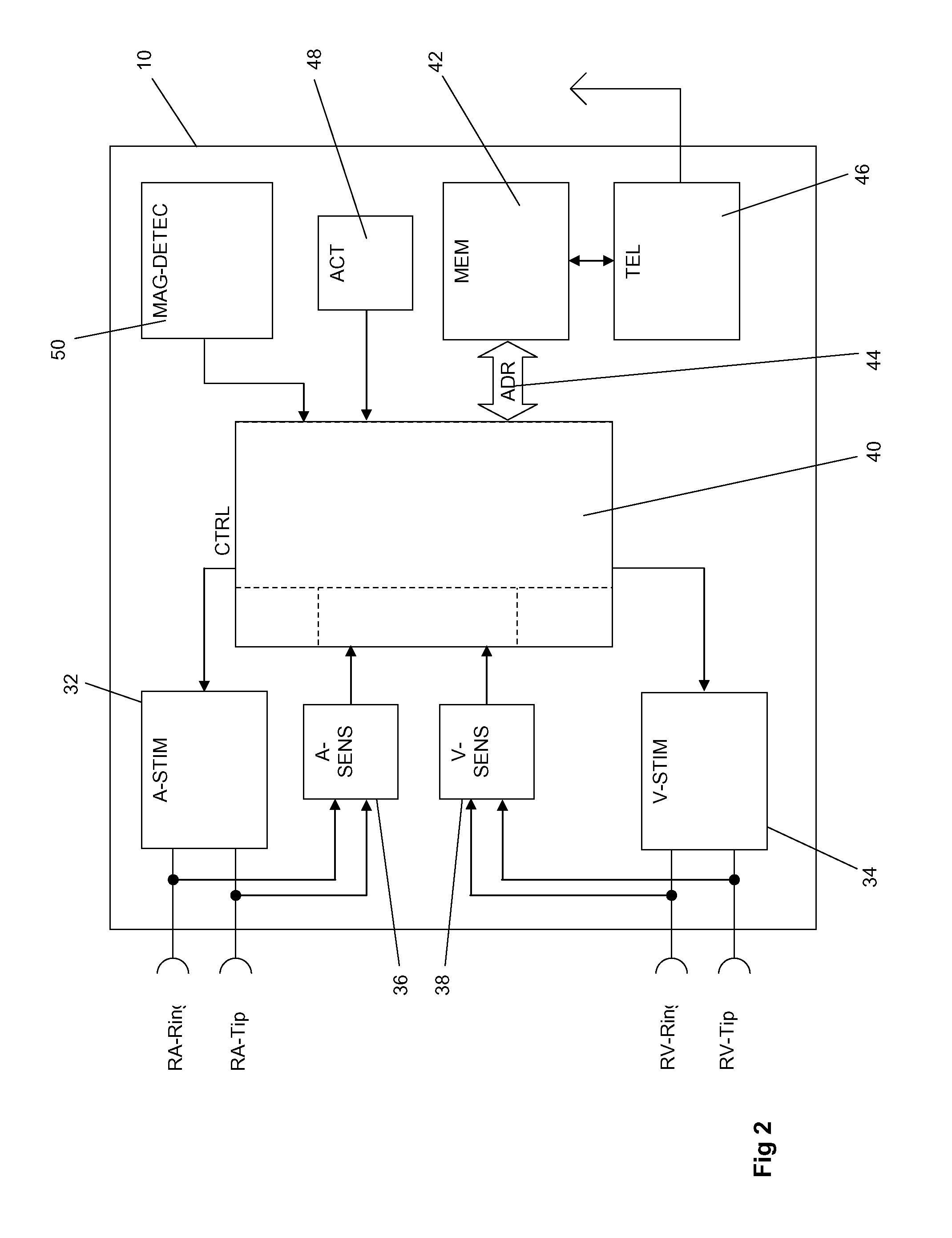
BACKGROUND OF THE INVENTION[0001]1. Field of the Invention[0002]The invention refers to an implantable medical device such as an implantable pacemaker or an implantable cardioverter / defibrillator (ICD).[0003]2. Description of the Related Art[0004]For more than 35 years, manufacturers have used a reed switch in cardiac implants to set the implant into a mode of operation that is commonly referred to as the magnet mode. The reed switch is normally open, and is closed when a permanent magnet is brought into close proximity to the implant.[0005]MRI is a diagnostic tool that has become increasingly popular, and is typically contraindicated for pacemaker and ICD patients due to possible mechanical forces, heating of leads, permanent damage to the electronic circuit or inappropriate therapy (e.g. loss of sensing or pacing at the UTR). An MRI has a static magnetic field that typically has a strength of 1.5 T, and newer MRI machines with fields of 3 T or higher are becoming available. When i...

Claims


Application Information

Patent Timeline
IPC IPC(8): A61N1/16
CPCA61N1/37G01R33/288G01R33/285A61N1/3718
Inventor DIGBY, DENNISWIGGINS, DAVIDBERTHELSDORF, RICHARD
Owner BIOTRONIX CRM PATENT AG
Learn More