
Non-invasive surgical ligation clip system and method of using

a ligation clip and non-invasive technology, applied in the field of ligation clips, can solve the problems of inability to reposition the clip after initial placement using the system in thronton et al., limited system, and relatively low elasticity of stainless steel

Active Publication Date: 2008-06-26
INTERRAD MEDICAL
View PDF1 Cites 87 Cited by
  • Summary
  • Abstract
  • Description
  • Claims
  • Application Information

AI Technical Summary

Benefits of technology

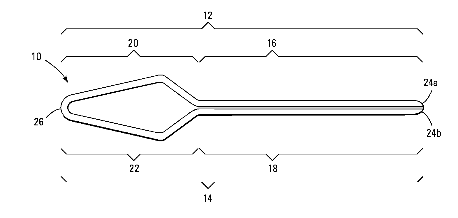
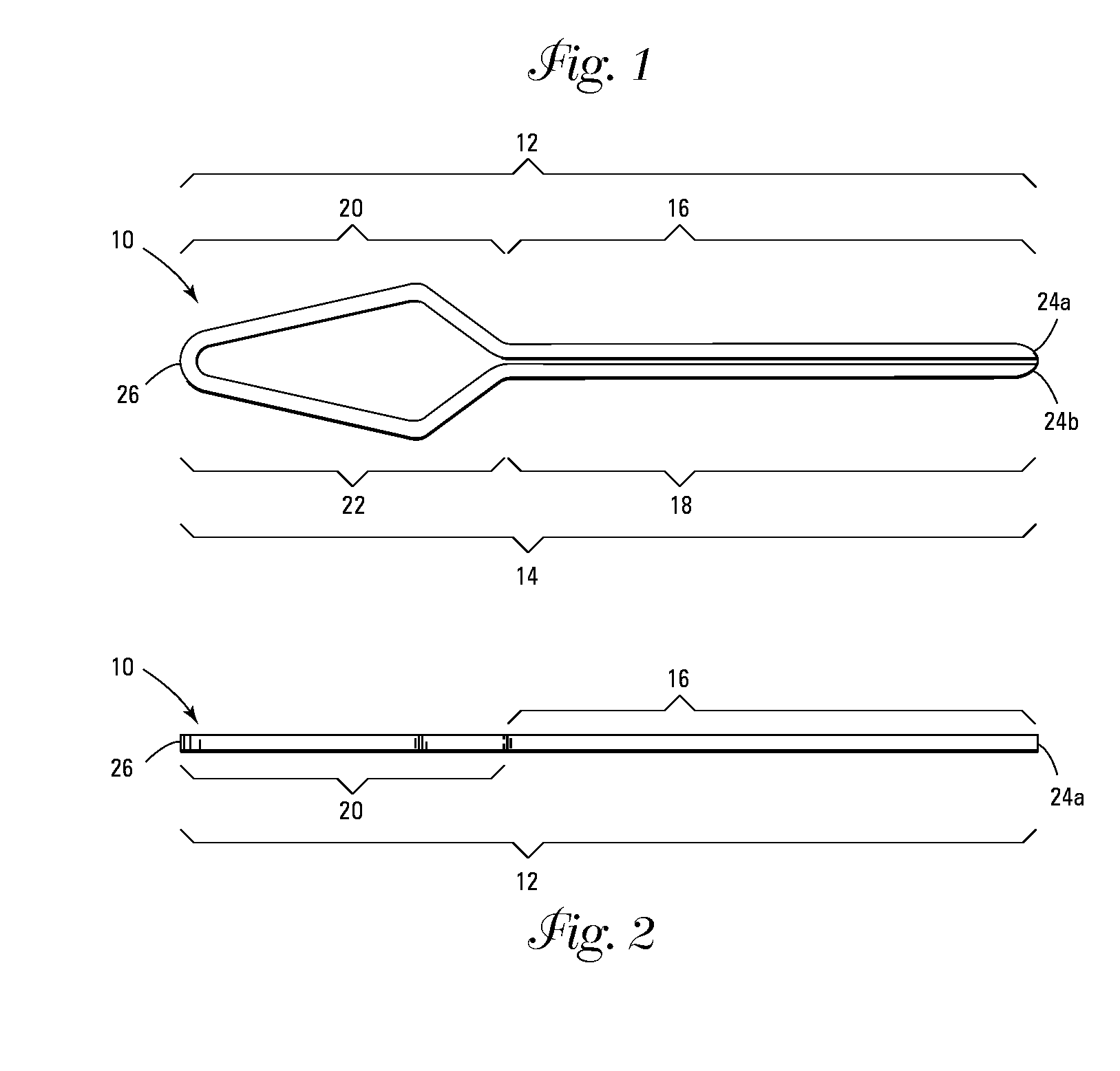
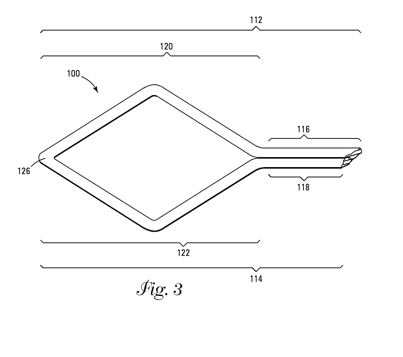
[0005]In one embodiment, the invention comprises a clip defining an unstressed shape. A first opposing jaw defines a clamping portion and a second opposing jaw defines a clamping portion. At least the first jaw defines a flexing portion having a different shape than the clamping portion of the first jaw, and the flexing portion is capable of being stressed so as to alter its shape and then resuming the unstressed shape when no longer being stressed. The first and second jaws are unattached at a first point of the clamping portions of the first and second jaws, which allows the first and second jaws to be able to separate apart from each other. When the flexing portion of the first jaw is stressed so as to alter its shape, the clamping portion of the first jaw moves in relation to the clamping portion of the second jaw. This causes the clamping portion of the first jaw to separate from the clamping portion of the second jaw.
[0006]In another embodiment, the invention comprises a clip defining an unstressed shape. The clip includes first and second opposing, longitudinally configured jaws, with the first and second jaws each defining a clamping portion and a flexing portion. The flexing portions are capable of being stressed so as to alter the unstressed shape of the flexing portions and then resuming he unstressed shape when the clip is no longer being stressed. The first and second jaws are unattached at a first point of the clamping portions which allows the first and second jaws to be able to separate apart from each other. Stressing the flexing portions of the first and second jaw toward each other therefore causes the clamping portions of the first jaw and second jaw to move away from each other.

Problems solved by technology

Non-invasive surgical procedures are increasingly popular among physicians, patients and insurance companies due to the decreased trauma and consequent healing time to the patient and decreased overall cost resulting from shortened hospital stays.
Such a system is, however, limited, to a rigid-shafted, straight-line instrument, and thus is inapplicable to many procedures where a more tortuous introductory path is required to access the treatment site.
A further disadvantage of stainless steel clips deals with the relatively low elasticity of stainless steel, which, when sufficiently bent, tends to remain in its bent position.
Thus, repositioning the clip after initial placement using the system in Thronton et al. is impossible without further open surgery.
The Adams device is limited to a rigid, straight-line hypotube delivery system, restricting the uses to which it may be directed.

Method used


Image

  • Non-invasive surgical ligation clip system and method of using
  • Non-invasive surgical ligation clip system and method of using
  • Non-invasive surgical ligation clip system and method of using

Examples


fifth embodiment

[0127]FIG. 10 shows the clip 500 which is similar to the clip 10 of FIG. 1 except for the lack of a flexing portion on the second jaw 514. This necessitates a longer clamping section 518 on the second jaw 514. The effect of only a single flexing portion 520 is to lessen the amount of force exerted by the clip 500 as a result of clamping. The ligation clip 500 defines at least a first 512 and second jaw 514, which have a longitudinal orientation. The first jaw 512 defines a clamping portion 516 and a flexing portion 520. The second jaw 514, however, defines a only a clamping portion 518. In this embodiment, the clamping portions 516, 518 are parallel with each other and should contact each other or nearly so when in a non-stressed state, only along that portion of their lengths where the clamping portion 516 of the first jaw 512 corresponds with the clamping portion 518 of the second jaw 514. Both first 512 and second 514 jaws define distal ends, 524a, 524b, which are not connected t...

sixth embodiment

[0128]FIG. 11 shows the clip 600, which is similar to the clip 500 shown in FIG. 10. The difference is that the clip 600 has an indentation 617 in the clamping portion 616 of the first jaw 612. The indentation 617 allows the clip 600 to exert less force against the clamped anatomical structure should less force be necessary. An additional advantage to having an indentation 617 is that it may help to guide or seat the structure and prevent the structure to be clamped (not shown) from being forced out of the clip 600 during the clamping procedure. The ligation clip 600 defines at least a first 612 and second jaw 614, which have a longitudinal orientation. The first jaw 612 defines a clamping portion 616 and a flexing portion 620. The second jaw 614, however, defines only a clamping portion 618. In this embodiment, the clamping portions 616, 618 should contact at least a portion of each other or nearly so when in a non-stressed state. Both first 612 and second 614 jaws define a distal ...

seventh embodiment

[0129]FIG. 13 shows the clip 800 that defines a first jaw 812 and a second jaw 814. The first jaw 812 defines a clamping portion 816 which terminates at a distal end 824a and a flexing portion 820. In a similar manner, the second jaw 814 defines a clamping portion 818, which terminates at a distal end 824b and a flexing portion 822. The first jaw 812 and second jaw 814 are joined at a proximal end 826 of the clip 800. The clamping portions 816, 818 cross over each other so as to exert a greater amount of force against a clamped anatomical structure (not shown in FIG. 13).

[0130]In a preferred embodiment, the clip 10, 100, 200, 300, 400, 500, 600, 800 is formed from a single length of nitinol wire that has been processed to exhibit superelasticity at human body temperature (around 37 degrees C.). The invention also contemplates forming the clip 10, 100, 200, 300, 400, 500, 600, 800 from nitinol processed to exhibit thermal shape memory characteristics at human body temperature. Nitino...


PUM

PropertyMeasurementUnit
clamping forceaaaaaaaaaa
shapeaaaaaaaaaa
cross-sectional shapeaaaaaaaaaa

Abstract

A surgical ligation clip capable of remote deployment through a cannula to engage an anatomical structure.

Description

CROSS-REFERENCE TO RELATED APPLICATION(S)[0001]This application is a continuation application of U.S. application Ser. No. 10 / 215,216, filed on Aug. 8, 2002 by Michael S. Rosenberg et al. and entitled “NON-INVASIVE SURGICAL LIGATION CLIP SYSTEM AND METHOD OF USING.” The disclosure of this earlier application is fully incorporated herein by reference.FIELD OF THE INVENTION[0002]The invention relates to ligation clips used in non-invasive surgical procedures.BACKGROUND[0003]Non-invasive surgical procedures are increasingly popular among physicians, patients and insurance companies due to the decreased trauma and consequent healing time to the patient and decreased overall cost resulting from shortened hospital stays. Such surgical procedures allow physicians to access remote regions of a patient's body to perform surgery without having to make major incisions in the patient's body. One form of non-invasive procedure requires the physician to create small incisions proximate the area u...

Claims


Application Information

Patent Timeline
Patent Type & Authority Applications(United States)
IPC IPC(8): A61B17/10A61B17/00A61B17/08A61B17/12A61B17/122A61L
CPCA61B17/12A61B17/122A61B17/10A61B2017/00867A61B17/083A61B17/1227A61B17/1285A61B2017/00862
Inventor ROSENBERG, MICHAEL S.CLAUDE, TIMOTHY J.
Owner INTERRAD MEDICAL
Learn More