
Video display device, video display system, and video display method

Active Publication Date: 2008-06-26
HISENSE VISUAL TECH CO LTD
View PDF2 Cites 42 Cited by
  • Summary
  • Abstract
  • Description
  • Claims
  • Application Information

AI Technical Summary

Benefits of technology

[0007]However, when nothing is displayed on the video display device in an initial connection procedure, the pro

Problems solved by technology

However, when nothing is displayed on the video display device in an initial connection procedure, the problem is not solved because even the OSD mode cannot be used even in a case when the above-stated art is applied.

Method used


Image

  • Video display device, video display system, and video display method
  • Video display device, video display system, and video display method
  • Video display device, video display system, and video display method

Examples


Embodiment Construction

[0017]Hereinafter, embodiments of the present invention are described with reference to the drawings.

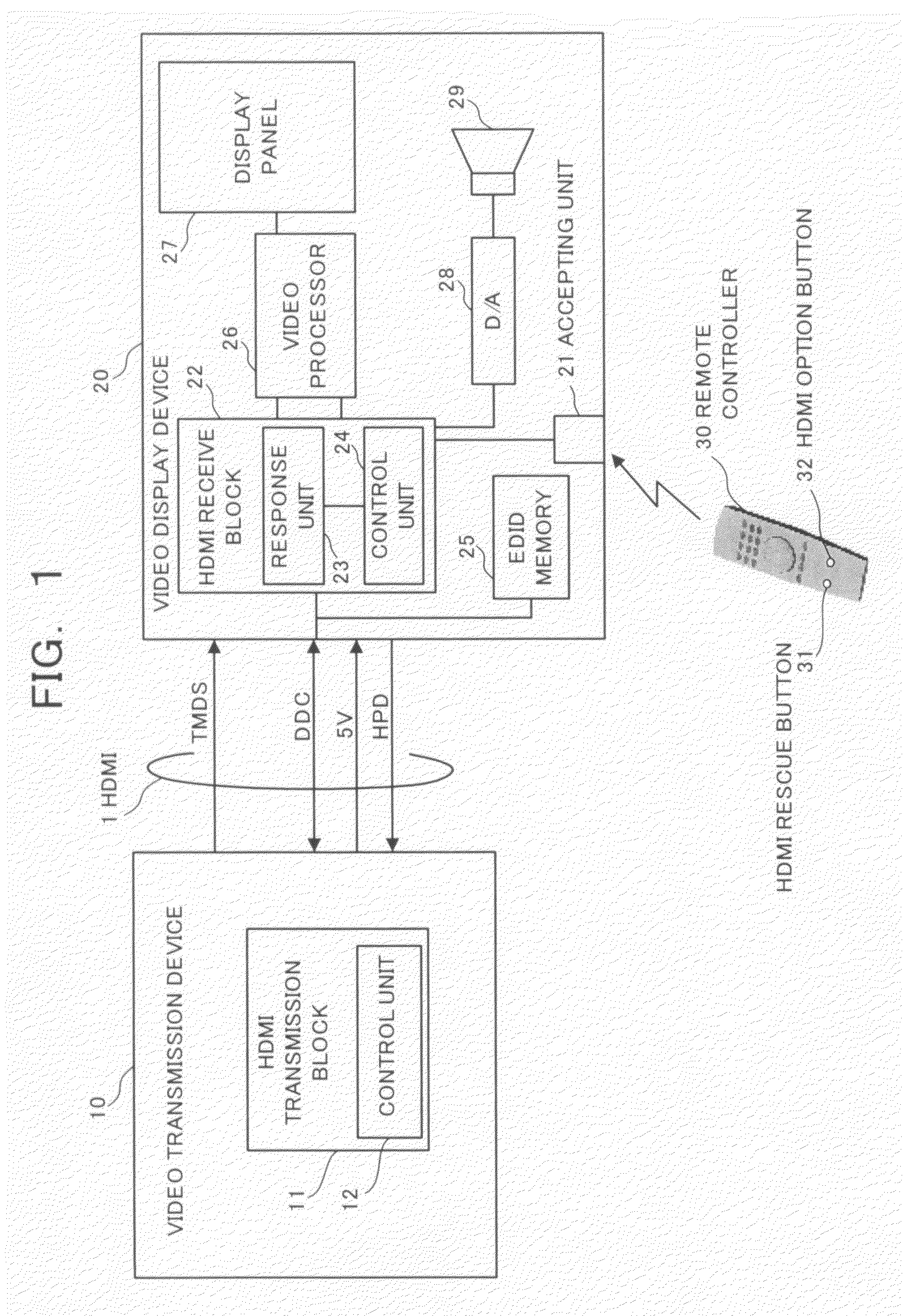
[0018]FIG. 1 is a block diagram showing a configuration of a video display system according to an embodiment of the present invention.

[0019]As shown in FIG. 1, the video display system is a system in which a video transmission device 10 and a video display device 20 are connected via a High Definition Multimedia Interface 1 (hereinafter referred to as “HDMI 1”).

[0020]The HDMI 1 is a digital signal transmission standard of video and sound, and used for a signal transmission between the video transmission device 10 compatible with the HDMI (DVD player, D-VHS recorder, set top box, camcorder, and so on) and the video display device 20 (TV, monitor, and so on).

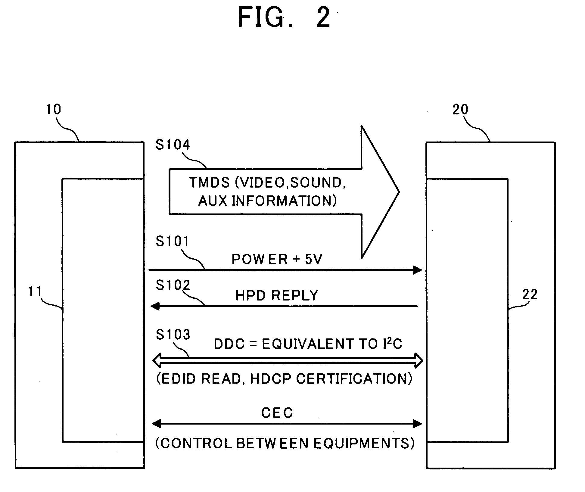
[0021]A TMDS line (Transition Minimized Differential Signaling line), 5 V_power line, Hot Plug Detect line (HPD line), DDC line (Display Data Channel line), CEC line, and so on are included in the HDMI 1.

[0022]In the TMDS line, sig...


PUM


Abstract

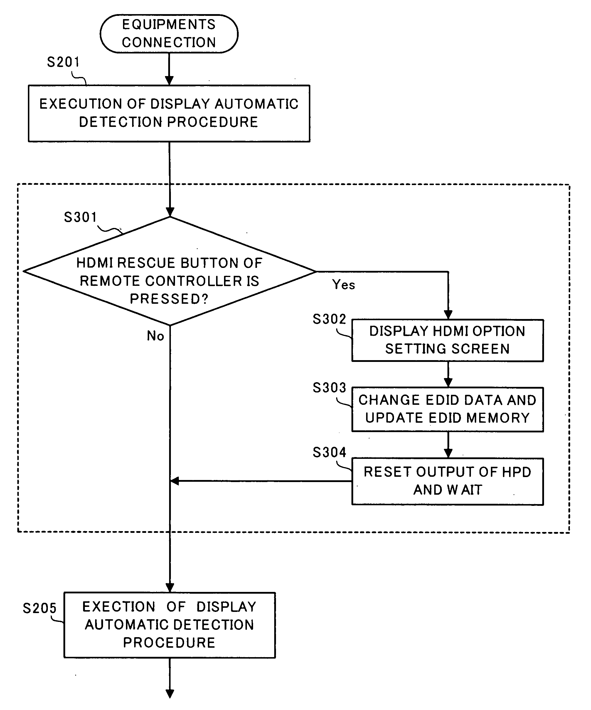
A video display system is a system in which a video transmission device 10 and a video display device 20 are connected via an HDMI 1. The video display device 20 includes an EDID memory 25 in which display side recognition data in plural formats are stored and one of them is set as an initial read data, a response unit 23 replying an HPD for a connection signal (power +5 V) inputted from the video transmission device 10 via the HDMI 1 and the initial read data of the EDID memory 25, and a control unit 24 resetting an output of the HPD after replacing the initial read data into the data of the EDID memory 25 in another format when a display recognition command from a remote controller 30 is accepted.

Description

CROSS-REFERENCE TO THE INVENTION[0001]This application is based upon and claims the benefit of priority from the prior Japanese Patent Application No. 2006-346397, filed on Dec. 22, 2006; the entire contents of which are incorporated herein by reference.BACKGROUND OF THE INVENTION[0002]1. Field of the Invention[0003]The present invention relates to a video display device, a video display system, and a video display method connected to a video transmission device such as, for example, a DVD player, digital tuner, and game machine via a digital interface such as an HDMI or DVI.[0004]2. Description of the Related Art[0005]In equipments equipped with a digital interface such as an HDMI, DVI, they have a mechanism that a video transmission device reads in an EDID (Extended Display Identification Data) of a video display device by using a DDC line (Display Data Channel line), reads displayable video format information of the video display device written in the EDID, and transmits a video ...

Claims


Application Information

Patent Timeline
IPC IPC(8): H04N5/50
CPCH04N5/772H04N5/85H04N5/775
Inventor SUZUKI, SHINOBU
Owner HISENSE VISUAL TECH CO LTD
Learn More