
System and method for reducing wake

a technology of aeromechanical stress and system, applied in the direction of machines/engines, efficient propulsion technologies, air-flow influencers, etc., can solve the problems of noise generation, -stator wake, emanating from rotating machines, etc., to improve fluid flow mixing and mitigate a flow that interacts with the wak

Inactive Publication Date: 2008-06-26
GENERAL ELECTRIC CO
View PDF6 Cites 65 Cited by
  • Summary
  • Abstract
  • Description
  • Claims
  • Application Information

AI Technical Summary

Benefits of technology

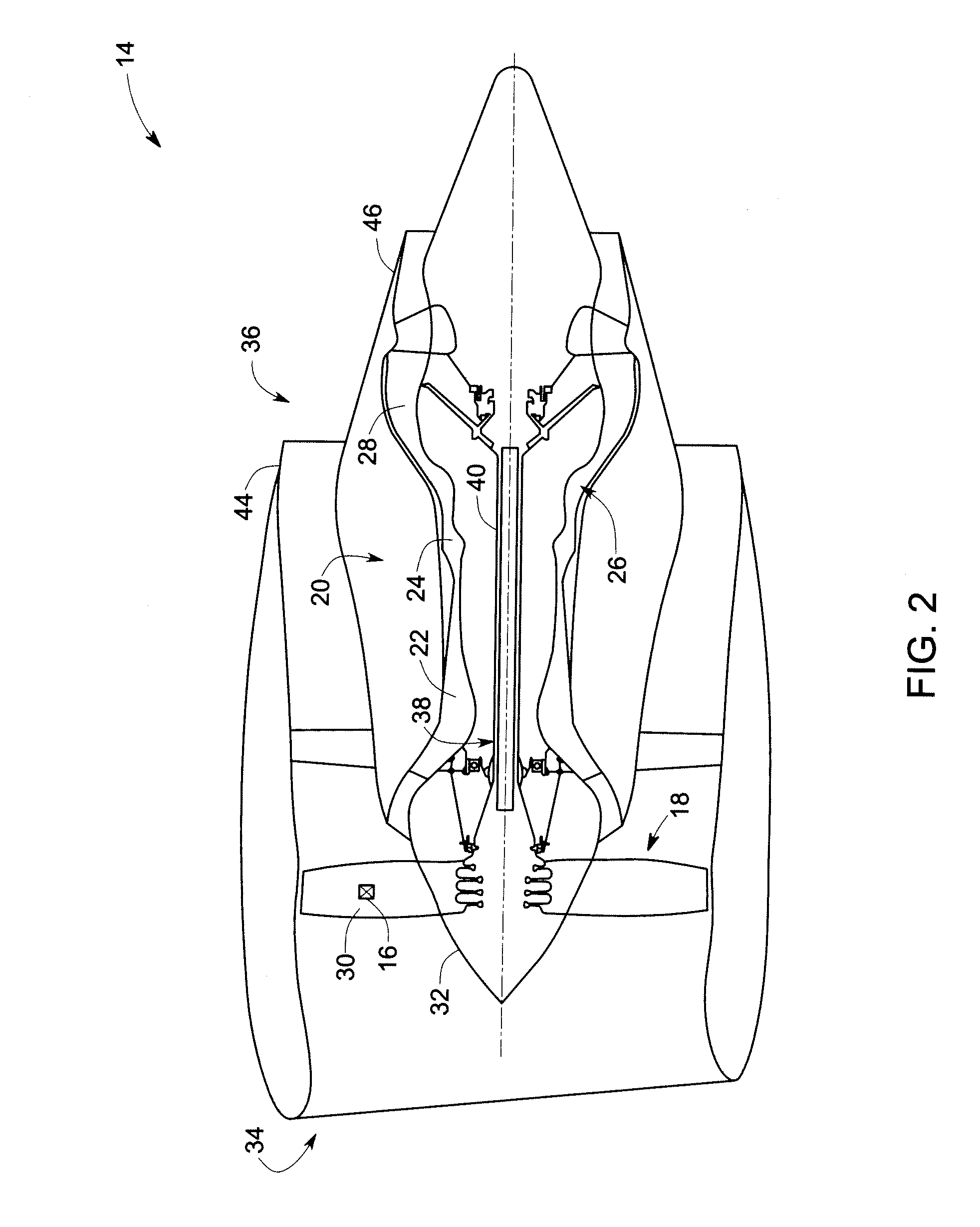
[0005]In accordance with one exemplary embodiment of the present invention, a rotary machine includes a first set of components and a second set of components disposed downstream within the fluid flow with respect to the first set of components. A fluid flow control system is coupled to the first set of components. The fluid flow control system includes an unsteady blower device that includes an aperture disposed upon a surface of the first set of components. The unsteady blower device is configured to perform unsteady blowing of a fluid from the aperture to enhance mixing in the fluid flow over the first set of components in order to mitigate a wake in the flow that interacts with the second set of components.
[0006]In accordance with another exemplary embodiment of the present invention, a method of operating a rotary machine includes passing a fluid flow through the machine over a first set of components and a second set of components, the second set of components being disposed in the fluid flow downstream of the first set of components. The method also includes performing unsteady blowing of a fluid from a trailing edge of the first set of components via an unsteady blower device to enhance mixing in the fluid flow in order to mitigate a wake in the flow that interacts with the second set of components.

Problems solved by technology

In rotating machines, noise is generated due to interaction of air or fluid with the machine's operative surfaces.
A significant cause of noise emanating from rotating machines is due to the wakes that are generated behind stationary components (e.g., frames, struts, vanes etc) and rotating components (fans, rotors etc), which then interact with downstream components (causing a rotor-stator wake interaction) and a resulting unsteady loading on the machine components.
In addition to noise, this wake interaction and related unsteady aeromechanical loading on downstream structures produces stress and is a cause of high-cycle fatigue of rotor blades.
However, the system costs of the wake-filling concept have proven to be too high to be integrated with any current commercial aircraft engines.
However, this arrangement has limited effectiveness and also leads to larger system costs.

Method used


Image

  • System and method for reducing wake
  • System and method for reducing wake
  • System and method for reducing wake

Examples


Embodiment Construction

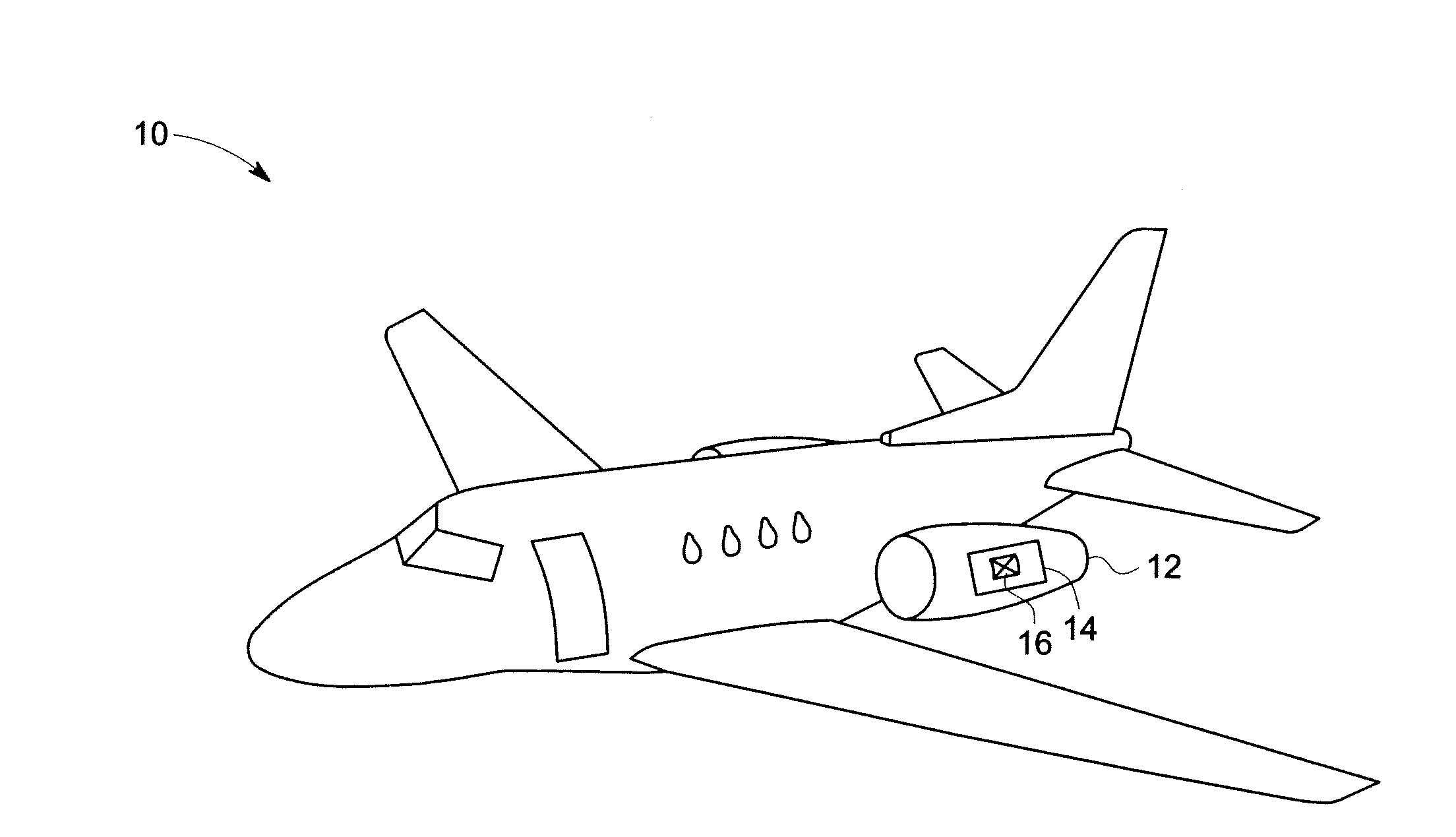
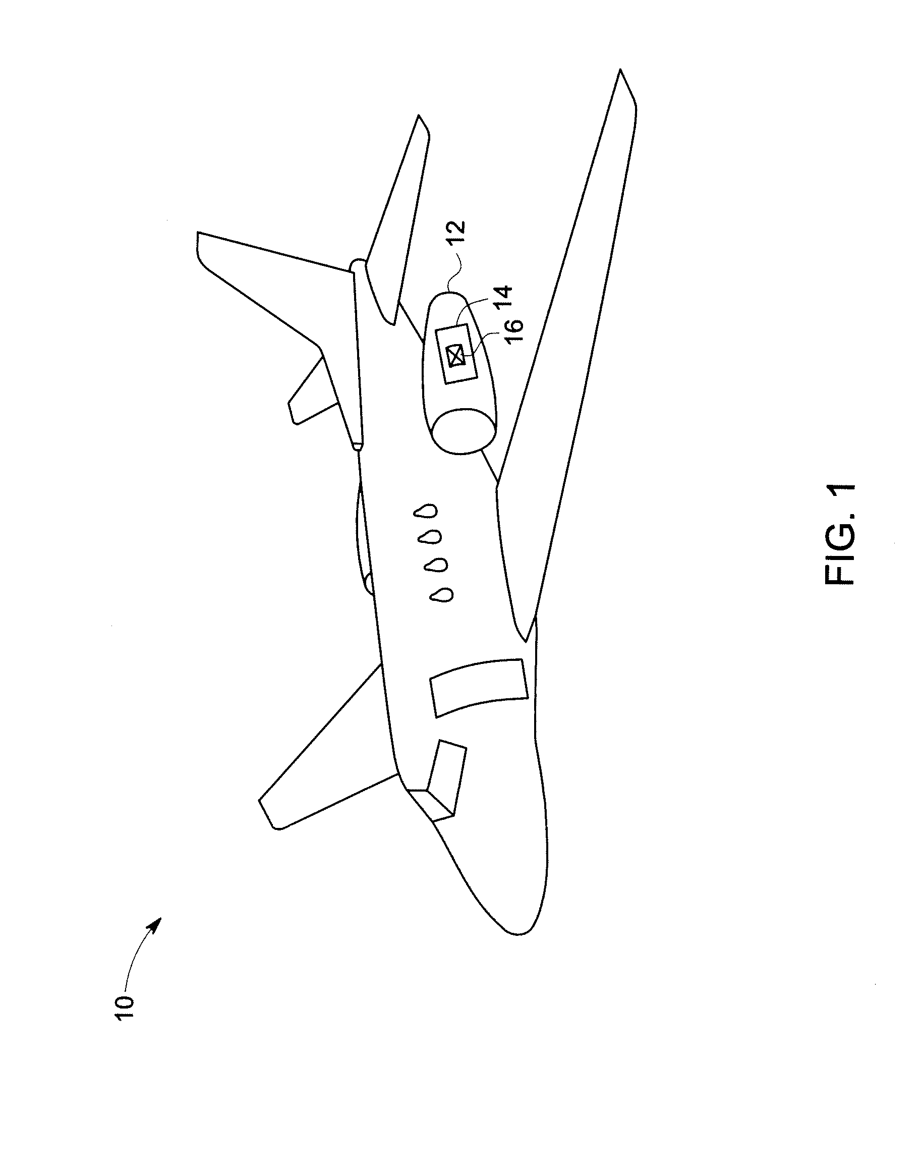
[0020]How control techniques may be used to improve aerodynamics and general flow performance in a variety of applications, including aircraft engines, aircraft wings, various airfoils, industrial ducts, pneumatic transports, boats, submarines, marine projectiles, various parts of wind turbines such as stalls, lifts, gusts and so forth. As discussed in detail below, embodiments of the present invention provide a rotary machine having two sets of components rotatable with respect to one another. In certain embodiments, these components may include rotors and stators. As used herein, the term “stator” may include such elements as stator blades, outlet guide vanes, blowing struts, or the like. The term “rotor” may include one or more rotor blades, fan blades, or other rotating components within devices such as gas turbine engines. In a typical gas turbine engine, rotors and stators are arranged in such a way that airflow past an upstream component will tend to produce a wake that impin...


PUM


Abstract

A machine includes an unsteady blower device, such as a synthetic jet actuator, disposed such that an aperture of the blower is disposed upon the trailing edge of the machine component. The unsteady blower device is actuated to perform unsteady blowing of a fluid from the aperture in order to enhance turbulent mixing in the flow to mitigate undesirable wakes that interact with downstream components. Such unsteady blower devices facilitate momentum transfer or unsteady excitation or energy addition into the flow through the machine via direct injection of additional fluid.

Description

BACKGROUND[0001]The invention relates generally to techniques for reducing noise and aeromechanical stress associated with machine wakes, and more particularly relates to a system and method for reducing noise and aeromechanical stress associated with airflow over components of machines.[0002]In rotating machines, noise is generated due to interaction of air or fluid with the machine's operative surfaces. Examples of such rotating machines include aircraft engines, fluid pump impellers, pump inlets, pump diffusers, marine propellers, air conditioners, high speed blowers, and the like. A significant cause of noise emanating from rotating machines is due to the wakes that are generated behind stationary components (e.g., frames, struts, vanes etc) and rotating components (fans, rotors etc), which then interact with downstream components (causing a rotor-stator wake interaction) and a resulting unsteady loading on the machine components. In addition to noise, this wake interaction and ...

Claims


Application Information

Patent Timeline
Patent Type & Authority Applications(United States)
IPC IPC(8): F15C3/00
CPCB64C21/04B64C21/08F01D5/145F01D5/147F01D5/26B64C2230/18F05D2270/172F15B21/12Y02T50/166Y02T50/673F02K3/00Y10T137/2202Y02T50/10Y02T50/60
Inventor GUPTA, ANURAGSHIEH, CHINGWEI MICHAELSADDOUGHI, SEYED GHOLAMALI
Owner GENERAL ELECTRIC CO
Learn More