
Methods and system for jointless track circuits using passive signaling

a jointless track and passive signaling technology, applied in the direction of railway signalling, railway signalling and safety, railway components, etc., can solve the problems of low cost of installation and maintenance of electrically insulating materials, limited distance between signaling points, and attenuation of an applied voltage between rails, so as to improve the communication range of data and low cost

Inactive Publication Date: 2008-06-19
GENERAL ELECTRIC CO
View PDF5 Cites 39 Cited by
  • Summary
  • Abstract
  • Description
  • Claims
  • Application Information

AI Technical Summary

Benefits of technology

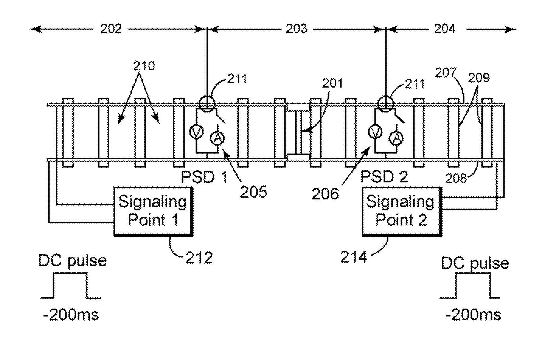
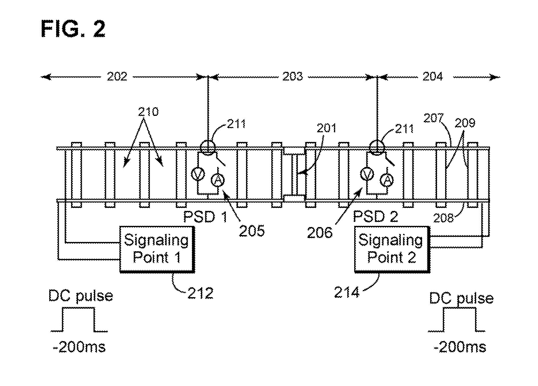
[0011]Each PSD may include a switch (“PSD switch”). When the PSD switch is closed, the PSD can sense current provided by the signaling point through the rails. When the switch is open, the PSD can sense voltage across the rails applied by the signaling point. The PSD can communicate with neighboring signaling points or PSDs using the switch to modulate the voltage or the current provided by the signaling point. This is analogous to a passive RFID tag, which receives its power through the RF interrogation waveform sent by a reader, and modulates the interrogation waveform to send information back to the reader. Using this approach, low cost voltage and current sensing PSDs can be installed along the track (without needing to lay extra cables) and powered by a signaling point located miles away. Use of PSDs configured as described herein improves the communication range of data because each PSD can communicate data to its neighbors, which can relay the data back to the signaling point. The signaling point can then relay the data to the cab of a train or to a control point at the railroad.

Problems solved by technology

First, the pieces of electrically insulative material are expensive to install and maintain, and tend to deteriorate over time.
Additionally, the distance between signaling points is limited because leakage current flows through the ballast (e.g., the material under and / or between the rails that forms or rests on the railroad bed), thereby attenuating an applied voltage between the rails.
A disadvantage is that this fixed threshold represents a joint optimization for detecting track occupancy, broken rails, and communication, but is typically not optimized for any one function.
The problem with this type of jointless track circuit is that the signaling points can be located only about 0.5 miles apart due to the low-pass filtering effect of the rail inductance.
This type of circuit is not practical for rail applications requiring block lengths longer than 0.5 miles.

Method used


Image

  • Methods and system for jointless track circuits using passive signaling
  • Methods and system for jointless track circuits using passive signaling
  • Methods and system for jointless track circuits using passive signaling

Examples


Embodiment Construction

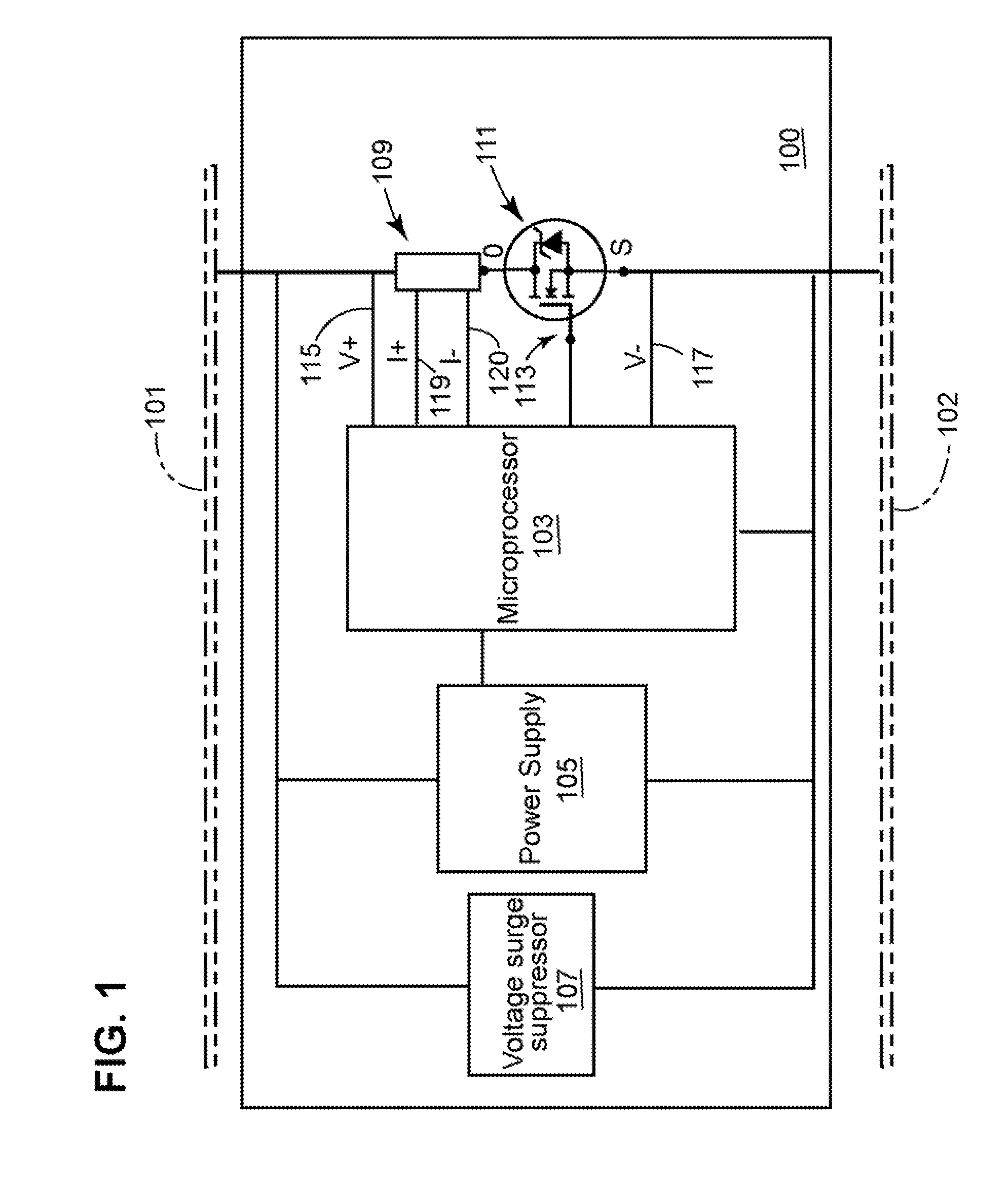
[0027]FIG. 1 is a diagram of a new passive signaling device (“PSD”) 100 configured configured to detect a presence of a train or a presence of a broken rail within a predetermined section (e.g., block) of railroad track (hereinafter “track”). The PSD 100 may also be configured to communicate track data to a signaling point. Track data includes, but is not limited to: data indicating a train is present within a predetermined block of track; data indicating a train is not present within the predetermined block of track; data indicating a train is approaching or receding from a PSD; data indicating a rail (or rails) within the predetermined block of track has a break; and data indicating there are no breaks with the rail (or rails) within the predetermined block of track.

[0028]Referring to FIG. 1, a PSD may include a low-power control device 103, a power supply105, a voltage surge protector 107, a current sensor 109, and a PSD switch 111. The control device 103 may be any suitable type...


PUM


Abstract

The present disclosure describes methods and systems for connecting passive signaling devices (“PSDs”) to a railroad track and using the PSDs to optimize the amplitude, modulation, coding, and frequency of waveforms that applied to the track (by signaling points) for at least three track circuit functions: detecting trains, detecting broken rails, and communicating between signaling points and PSDs.

Description

BACKGROUND[0001]1. Field of the Invention[0002]The present disclosure relates to railroads generally, and more particularly, to methods and systems for using passive signaling in jointless track circuits.[0003]2. Discussion of Related Art[0004]Conventional track circuits use signaling points to monitor a block of railroad track for the presence of trains and broken rails. Signals transmitted and / or received by the signaling points indicating the block state (e.g., whether occupied, empty, or containing a broken rail) are used to directly control the wayside signal aspects, and to send information to the train (via cab signals in the rail) or a central office (via remote communication links).[0005]Blocks of railroad track are separated from each other by insulative joints (e.g., pieces of electrically insulative material), which are interposed between sections of rail. Use of jointed tracks, however, has several disadvantages. First, the pieces of electrically insulative material are...

Claims


Application Information

Patent Timeline
IPC IPC(8): B61L23/34
CPCB61L23/044B61L1/181
Inventor TOMLINSON, HAROLD WOODRUFFHERSHEY, JOHN ERIKFRIES, JEFFREY MICHAEL
Owner GENERAL ELECTRIC CO
Learn More