
Monolithic acoustically-treated engine nacelle inlet panels

a technology of engine nacelle and inlet panel, which is applied in the direction of machines/engines, efficient propulsion technologies, instruments, etc., can solve the problems of high noise levels, low noise reduction efficiency, and inability to replace routine engines for lower sound generation levels, etc., and achieve the effect of reducing nois

Active Publication Date: 2008-06-12
THE BOEING CO
View PDF15 Cites 23 Cited by
  • Summary
  • Abstract
  • Description
  • Claims
  • Application Information

AI Technical Summary

Benefits of technology

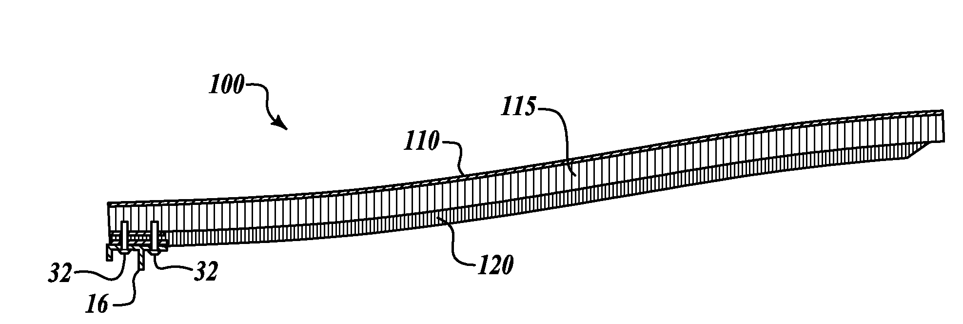
The patent describes a new type of acoustic panel for aircraft engine nacelles that can be used to reduce noise. These panels are made up of layers that form a single, integrated structure. They are designed to be attached to the engine nacelle without any additional structure that could generate noise. The panels can be retrofitted to existing engines or used on new engines. The panel has a perforated film, a sound-attenuating core, and a structural layer with through-holes that can be used to attach the panel to the engine nacelle. The panels are strong enough to withstand the conditions of use and can help reduce noise in the engine.

Problems solved by technology

Accordingly, noise abatement is a complex issue.
For example, reducing engine speed may reduce engine noise, but may be hazardous when an aircraft is fully loaded, taking off from a higher altitude airport under hot weather conditions.
Certain airports may have relatively short runways for take off, necessitating high engine loads which result in higher noise levels.
With so many aircraft already in service, and with such a high investment in existing engines that have a long useful life span, routine engine replacement for lower levels of sound generation may not be commercially feasible.
One of the sources of engine noise is the engine nacelle inlet area.
The non-acoustically treated areas do not, therefore, provide noise attenuation like the other areas of the panels.
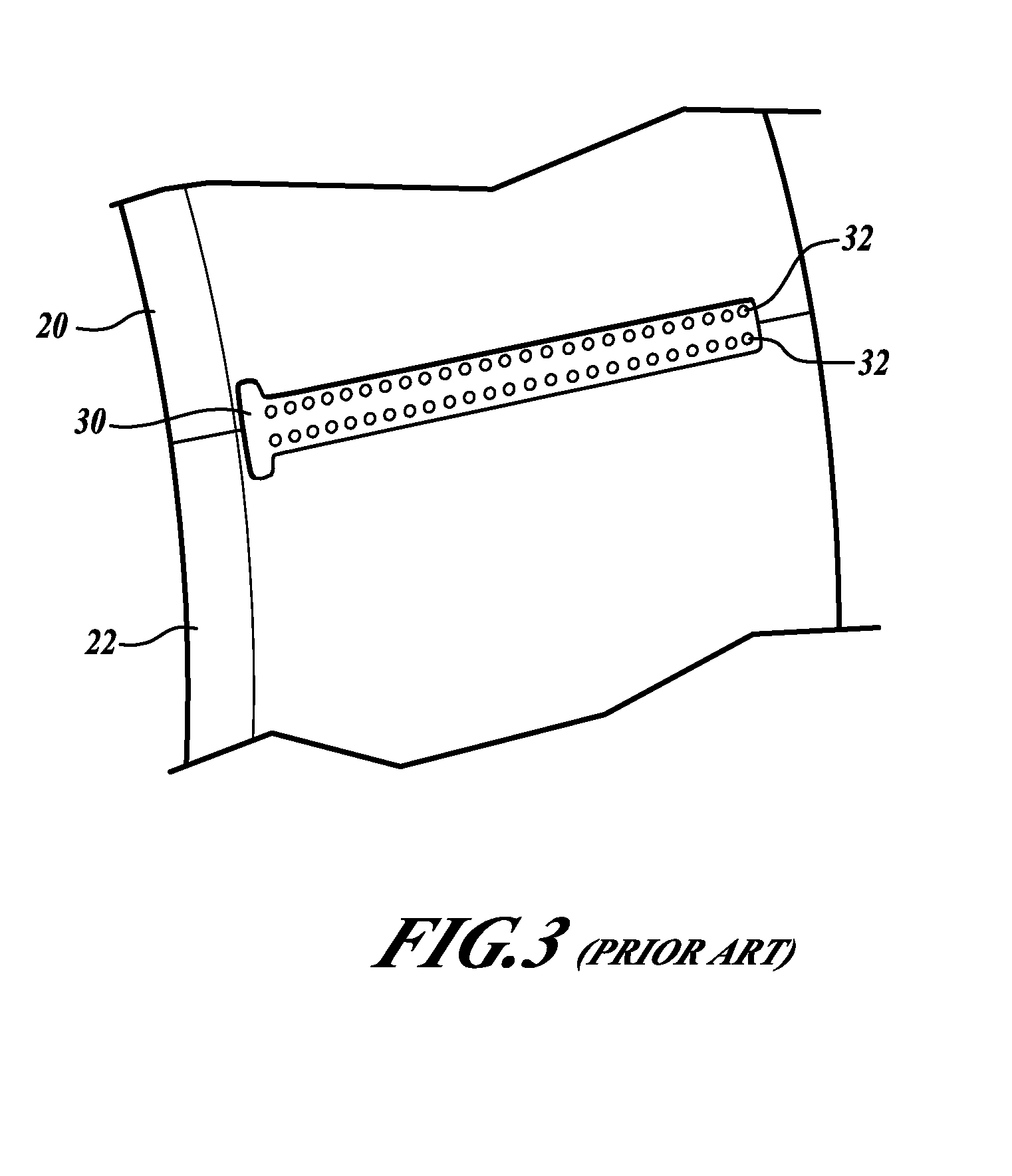
These fasteners create discontinuities in the otherwise smooth surface at the nacelle inlet thereby presenting a further source of noise at the nacelle inlet.

Method used


Image

  • Monolithic acoustically-treated engine nacelle inlet panels
  • Monolithic acoustically-treated engine nacelle inlet panels
  • Monolithic acoustically-treated engine nacelle inlet panels

Examples


Embodiment Construction

[0016]The following detailed description is merely illustrative in nature and is not intended to limit the invention or the application and uses of the invention. Furthermore, there is no intention to be bound by any expressed or implied theory presented in the preceding technical field, background, brief summary or the following detailed description.

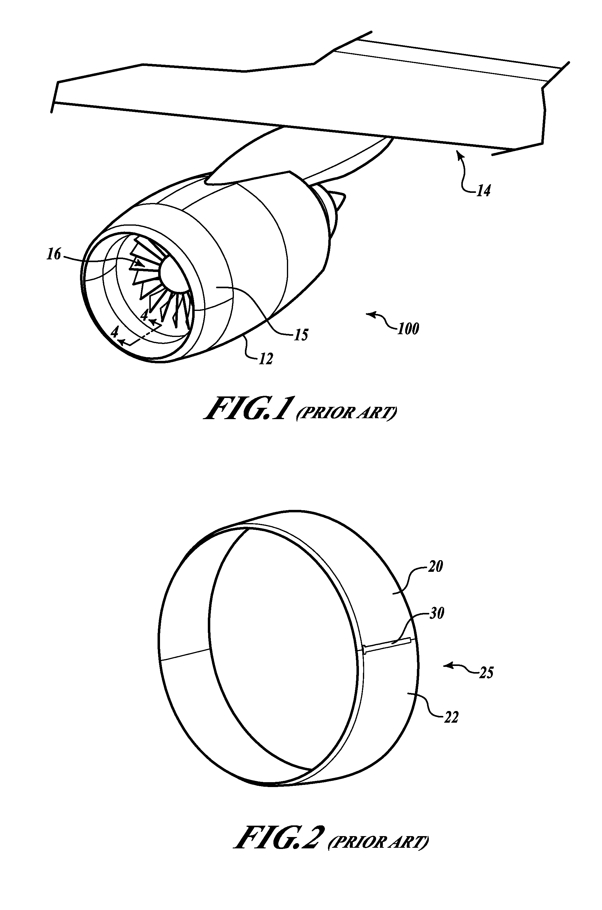
[0017]As a preliminary matter, FIG. 1 illustrates an aircraft engine 10 encased in a nacelle 12 and attached to a wing 14. The engine 10 has a turbine 16 that rotates to pull air into the engine through the front end inlet 15 of the nacelle 12. The high volume and speed of air rushing in through the nacelle inlet 15 creates noise. In an effort to abate this noise, nacelle inlet 15 has an acoustic panel 25 comprised of two halves 20, 22 located at the inlet of the nacelle 12.

[0018]As shown in FIG. 2, the acoustic panel halves 20, 22 are shaped as semi-circles, and are joined together at their ends to form a circular shaped panel 25. Pane...


PUM


Abstract

An acoustic, noise-attenuating panel for an aircraft engine nacelle inlet. The panel includes at least three layers: (a) a perforated film; (b) a sound attenuating core; and (c) a structural layer. The structural layer has through-holes adapted for receiving fasteners that are configured to engage structure of an engine nacelle. The structural layer is fabricated, at least at its ends, of a material sufficiently strong so that when fasteners are engaged in the through-holes in the layer's ends, the fasteners retain the acoustic panel in a nacelle inlet under conditions of use. Alternatively, or in addition, the structural layer ends may be reinforced at the through-holes with reinforcing strips.

Description

TECHNICAL FIELD[0001]The present disclosure relates generally to aircraft engine noise reduction. More particularly, the disclosure relates to engine noise reduction through use of acoustically-treated engine nacelle inlet panels.BACKGROUND[0002]Aircraft noise reduction is an ongoing concern at airports around the world, as air traffic continues to increase and as people living near airports, or along aircraft take-off and landing flight paths, express concerns about aircraft noise. Accordingly, most airport facilities have regulations that set noise limits and that control aircraft flight paths on take off and landing. Some airport facilities now provide financial incentives or restrict terminal privileges to encourage airlines to reduce noise even further.[0003]Aircraft noise has several sources, for example engine noise, landing gear orientation upon take off and landing, aircraft aerodynamic effects, among others. Accordingly, noise abatement is a complex issue. A strategy for a...

Claims


Application Information

Patent Timeline
Patent Type & Authority Applications(United States)
IPC IPC(8): B64D33/02
CPCB64D2033/0206Y02T50/672F02C7/045Y02T50/60
Inventor STRUNK, JOHN T.SPIKER, BRADFORD S.
Owner THE BOEING CO
Learn More