
Power system with power converters having an adaptive controller

a technology of power converter and adaptive controller, which is applied in the direction of electric variable regulation, process and machine control, instruments, etc., can solve the problems of not considering constraints of the actual application (such, etc.) or the environment, and the operating efficiency approaches zero, so as to improve the operating efficiency

Active Publication Date: 2008-06-05
MYPAQ HLDG LTD
View PDF99 Cites 151 Cited by
  • Summary
  • Abstract
  • Description
  • Claims
  • Application Information

AI Technical Summary

Benefits of technology

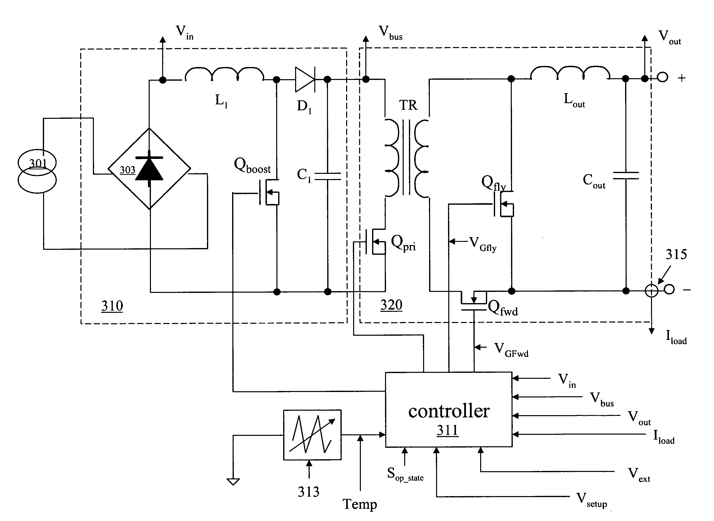
[0019]These and other problems are generally solved or circumvented, and technical advantages are generally achieved, by advantageous embodiments of the present invention, which include a power system having a power converter with an adaptive controller and method of operating the same. In one embodiment, the power system is coupled to a load and includes a power system controller configured to receive a signal indicating a system operational state of the load and select a power converter operational state as a function thereof. The power system also includes a power converter with a power switch configured to conduct for a duty cycle to provide a regulated output characteristic at an output thereof. The power converter also includes a controller configured to receive a command from the power system controller to enter the power converter operational state and provide a signal to control the duty cycle of the power switch as a function of the output characteristic and in accordance with the command, thereby regulating an internal operating characteristic of the power converter to improve an operating efficiency thereof as a function of the system operational state.

Problems solved by technology

In the limiting case wherein the load current approaches a small percentage of the maximum rated current of the power converter, the operating efficiency approaches zero due to the need to provide power for fixed internal loads such as the controller itself, for drivers, for internal high-frequency power switches, and for inherently dissipative circuit elements such as the magnetic core of a high-frequency transformer.
Thus, system considerations of achieving high operating efficiency have immediate effects on the applicability of a particular power converter design, and the associated price thereof in the marketplace.
While Jacobs performs efficiency optimization under actual operating conditions, the reference nonetheless fails to consider constraints of the actual application (such as described in a requirements document or operating specification document) or the environment during execution of the process of efficiency optimization, or a signal from an external source to enable, limit, or alter the optimization process.
However, this control mechanism merely changes a setpoint for an output characteristic of the power converter, and is not adapted to optimize the efficiency of the power converter at the signaled setpoint.
The aforementioned system may require a higher level of performance from the power converter during such periods of high criticality, which may compromise operating efficiency, but which may admit higher operating efficiency during substantial periods of time in the lower processing state.
Power conversion systems of the prior art have only partially responded to such system operational state considerations in the optimization of operating efficiency, particularly at a system level.
Accordingly, opportunities for further improvement in power converter operational efficiency have not been realized.
Considering limitations as described above, a controller for a power converter is presently not available for the more severe applications that lie ahead that depend on achieving higher operating efficiency for a particular operating characteristic constrained or controlled by an environmental parameter.
In addition, a controller for a power converter is presently not available that responds to a parameter measured after a manufacturing step for the particular power converter unit, or to a parameter measured after a manufacturing step on a representative power converter unit, or on power converter units in a representative run, to improve the operating efficiency thereof.

Method used


Image

  • Power system with power converters having an adaptive controller
  • Power system with power converters having an adaptive controller
  • Power system with power converters having an adaptive controller

Examples


Embodiment Construction

[0034]The making and using of the presently preferred embodiments are discussed in detail below. It should be appreciated, however, that the present invention provides many applicable inventive concepts that can be embodied in a wide variety of specific contexts. The specific embodiments discussed are merely illustrative of specific ways to make and use the invention, and do not limit the scope of the invention.

[0035]The present invention will be described with respect to exemplary embodiments in a specific context, namely, a power system including power converters with a controller and, more particularly, a controller for a power converter that regulates an output characteristic of the power converter at an output thereof that adaptively controls an internal operating characteristic of the power converter to increase power conversion efficiency in response to a parameter of the power converter measured after a manufacturing step and / or an environmental parameter of the power conver...


PUM


Abstract

A power system having a power converter with an adaptive controller. The power system is coupled to a load and includes a power system controller that receives a signal indicating a system operational state of the load and selects a power converter operational state as a function thereof. The power system also includes a power converter with a power switch that conducts for a duty cycle to provide a regulated output characteristic at an output thereof. The power converter also includes a controller that receives a command from the power system controller to enter the power converter operational state and provides a signal to control the duty cycle of the power switch as a function of the output characteristic and in accordance with the command, thereby regulating an internal operating characteristic of the power converter to improve an operating efficiency thereof as a function of the system operational state.

Description

[0001]This application is a continuation in part of, and claims priority to, U.S. patent application Ser. No. 11 / 607,325, entitled “Power Converter with an Adaptive Controller and Method of Operating the Same,” filed on Dec. 1, 2006, which application is incorporated herein by reference.TECHNICAL FIELD[0002]The present invention is directed, in general, to electronic power conversion and, more specifically, to a power system having power converters including a controller adapted to improve power conversion efficiency and method of operating the same.BACKGROUND[0003]A switch-mode power converter (also referred to as a “power converter”) is a power supply or power processing circuit that converts an input voltage waveform into a specified output voltage waveform. Controllers associated with the power converters manage an operation thereof by controlling the conduction periods of power switches employed therein. Generally, the controllers are coupled between an input and output of the ...

Claims


Application Information

Patent Timeline
IPC IPC(8): H02M3/335
CPCH02M1/4225H02M3/33507Y02B70/1475H02M2001/007Y02B70/126H02M3/33592Y02B70/10H02M1/007
Inventor ARTUSI, DANIEL A.FOSLER, ROSSROZMAN, ALLEN F.
Owner MYPAQ HLDG LTD
Learn More