
Mode-Switching Cam Follower

a cam follower and cam technology, applied in non-mechanical valves, valve details, valve arrangements, etc., can solve the problems of difficult implementation of cam profile switching technologies in various valvetrain settings, actuation of roller finger decoupling mechanisms, and power demand on the engin

Inactive Publication Date: 2008-06-05
FORD GLOBAL TECH LLC
View PDF10 Cites 61 Cited by
  • Summary
  • Abstract
  • Description
  • Claims
  • Application Information

AI Technical Summary

Benefits of technology

[0002]One method of implementing cam profile switching in a roller finger follower valvetrain has been to utilize a “drop finger” follower, wherein the roller finger is movably coupled to the follower body in such a manner that the finger can be operated in either a coupled mode, in which the roller finger is locked in position relative to the follower body, or in a decoupled mode, in which the roller finger is decoupled from and allowed to move relative to the follower body. This allows the cam and valve to have different lifts, depending upon whether the roller finger is coupled to or decoupled from the follower body.
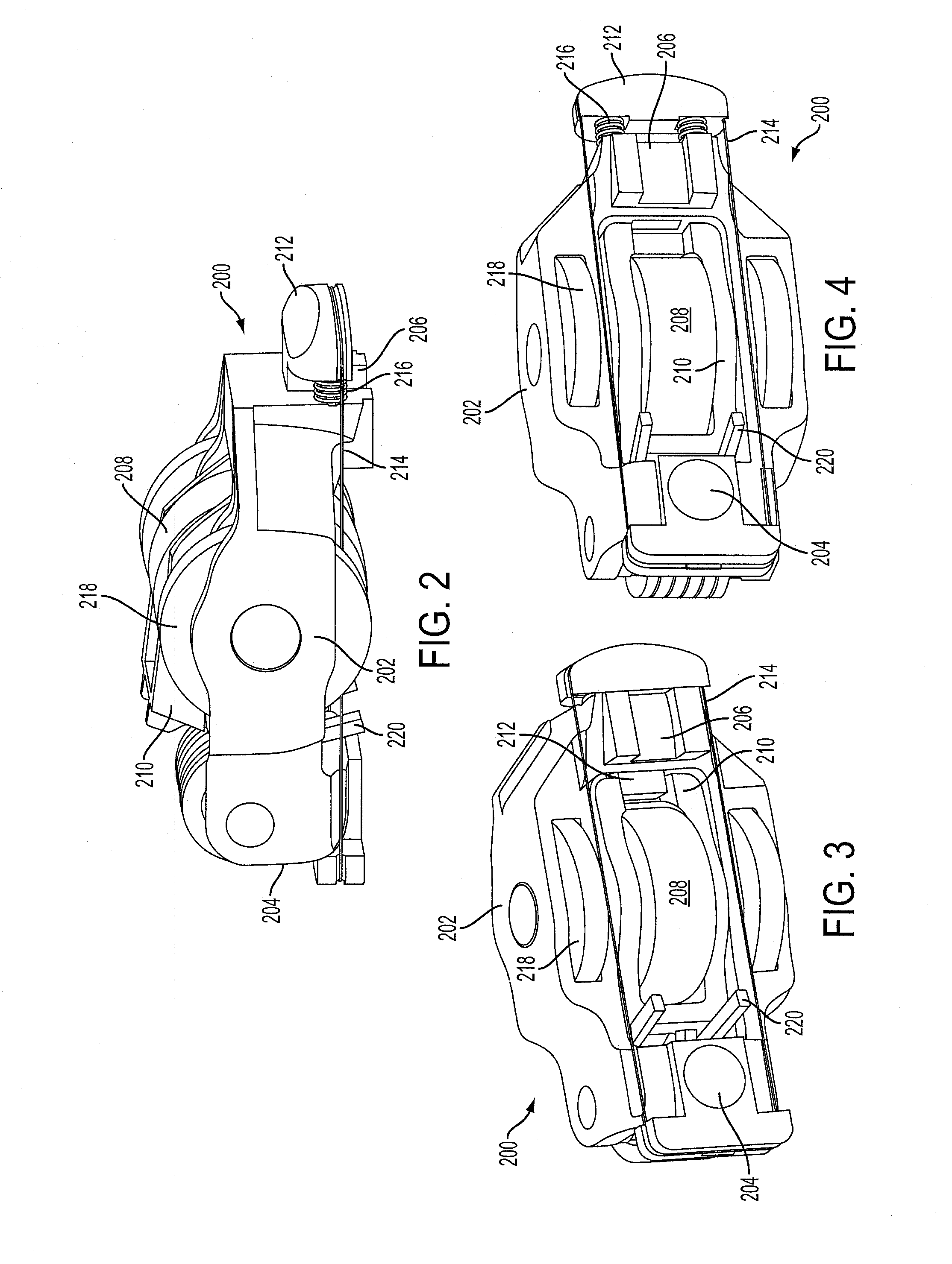
[0004]The inventors herein have realized that the above-described problems may be addressed through the use of a mode-switching cam follower having a body, a cam contact movably coupled to the body, a latch member movably coupled to the body, wherein the latch member is movable between a coupled position in which the cam contact is held in a fixed relation to the body by the latch member and a decoupled position in which the cam contact is decoupled from the latch member and movable relative to the body, and an actuator in communication with the latch member, wherein the actuator comprises a shape memory alloy member. In some embodiments, the cam contact includes a roller finger, while in other embodiments includes a sliding contact. Such a mode-switching cam follower may allow actuation of the latch member while avoiding problems with the size and power demands found in other actuation systems.

Problems solved by technology

However, cam profile switching technologies have been difficult to implement in various valvetrain settings, such as roller finger follower valvetrains.
One difficulty that has been encountered in implementing roller finger follower valve systems involves actuation of the roller finger decoupling mechanism.
However, hydraulic systems may cause a power demand on the engine, as these systems require the oil pump to do additional work.
Likewise, solenoids used in electromechanical systems may be relatively large and bulky.

Method used


Image

  • Mode-Switching Cam Follower
  • Mode-Switching Cam Follower
  • Mode-Switching Cam Follower

Examples


Embodiment Construction

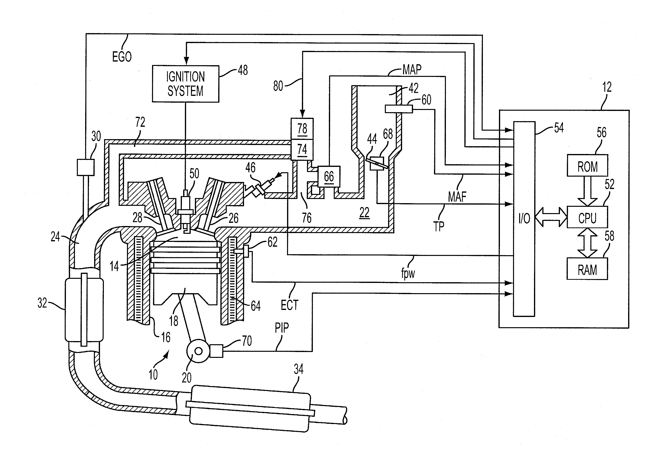
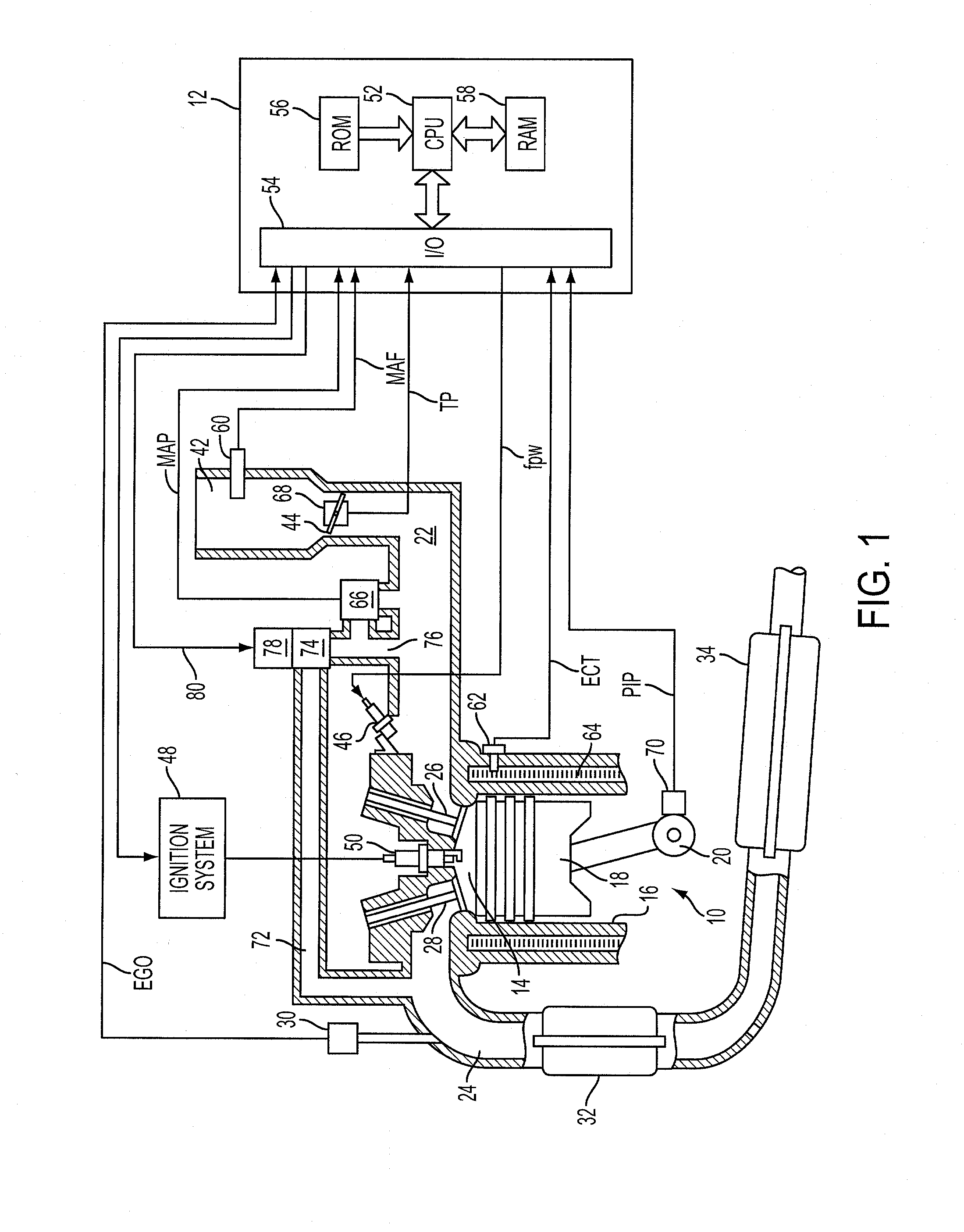
[0016]FIG. 1 shows a schematic depiction of an exemplary embodiment of an internal combustion engine 10. Engine 10 is depicted as a port-injection spark-ignition gasoline engine. However, it will be appreciated that the systems and methods disclosed herein may be used with any other suitable engine, including direct-injection engines, and compression ignition engines including but not limited to diesel engines.

[0017]Engine 10 typically includes a plurality of cylinders, one of which is shown in FIG. 1, and is controlled by an electronic engine controller 12. Engine 10 includes a combustion chamber 14 and cylinder walls 16 with a piston 18 positioned therein and connected to a crankshaft 20. Combustion chamber 14 communicates with an intake manifold 22 and an exhaust manifold 24 via a respective intake valve 26 and exhaust valve 28. An exhaust gas oxygen sensor 30 is coupled to exhaust manifold 24 of engine 10. A catalyst 32, such as a three-way catalyst, is connected to and receives...


PUM


Abstract

A mode-switching cam follower is disclosed, wherein the follower includes a body, a cam contact movably coupled to the body, a latch member movably coupled to the body, wherein the latch member is movable between a coupled position in which the cam contact is held in a fixed relation to the body by the latch member and a decoupled position in which the cam contact is decoupled from the latch member and movable relative to the body, and an actuator in communication with the latch member, wherein the actuator comprises a shape memory alloy member

Description

BACKGROUND AND SUMMARY [0001]Significant improvements in both fuel efficiency and performance of an internal combustion engine may be realized by selective switching of a cam profile. However, cam profile switching technologies have been difficult to implement in various valvetrain settings, such as roller finger follower valvetrains.[0002]One method of implementing cam profile switching in a roller finger follower valvetrain has been to utilize a “drop finger” follower, wherein the roller finger is movably coupled to the follower body in such a manner that the finger can be operated in either a coupled mode, in which the roller finger is locked in position relative to the follower body, or in a decoupled mode, in which the roller finger is decoupled from and allowed to move relative to the follower body. This allows the cam and valve to have different lifts, depending upon whether the roller finger is coupled to or decoupled from the follower body.[0003]One difficulty that has been...

Claims


Application Information

Patent Timeline
IPC IPC(8): F01L1/047
CPCF01L13/0021F01L1/185
Inventor RILEY, WILLIAMZAGATA, MARKSCHRADER, MICHAELMCCONVILLE, GREGORY
Owner FORD GLOBAL TECH LLC
Learn More