
Dynamic enablement and customization of tracing information in a data processing system

a data processing system and dynamic enablement technology, applied in the field of data processing system tools, can solve the problems of adversely affecting system operation, tracing activity itself consuming system resources, and not typically enabled trace points, so as to achieve the effect of not adversely affecting the overall system performan

Inactive Publication Date: 2008-05-29
IBM CORP
View PDF5 Cites 90 Cited by
  • Summary
  • Abstract
  • Description
  • Claims
  • Application Information

AI Technical Summary

Benefits of technology

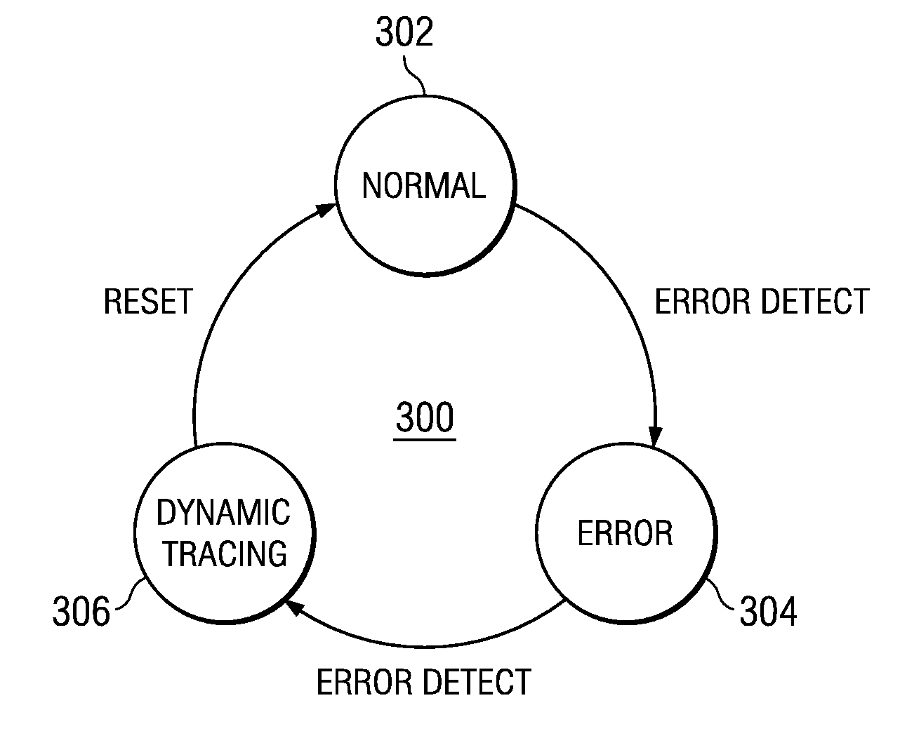
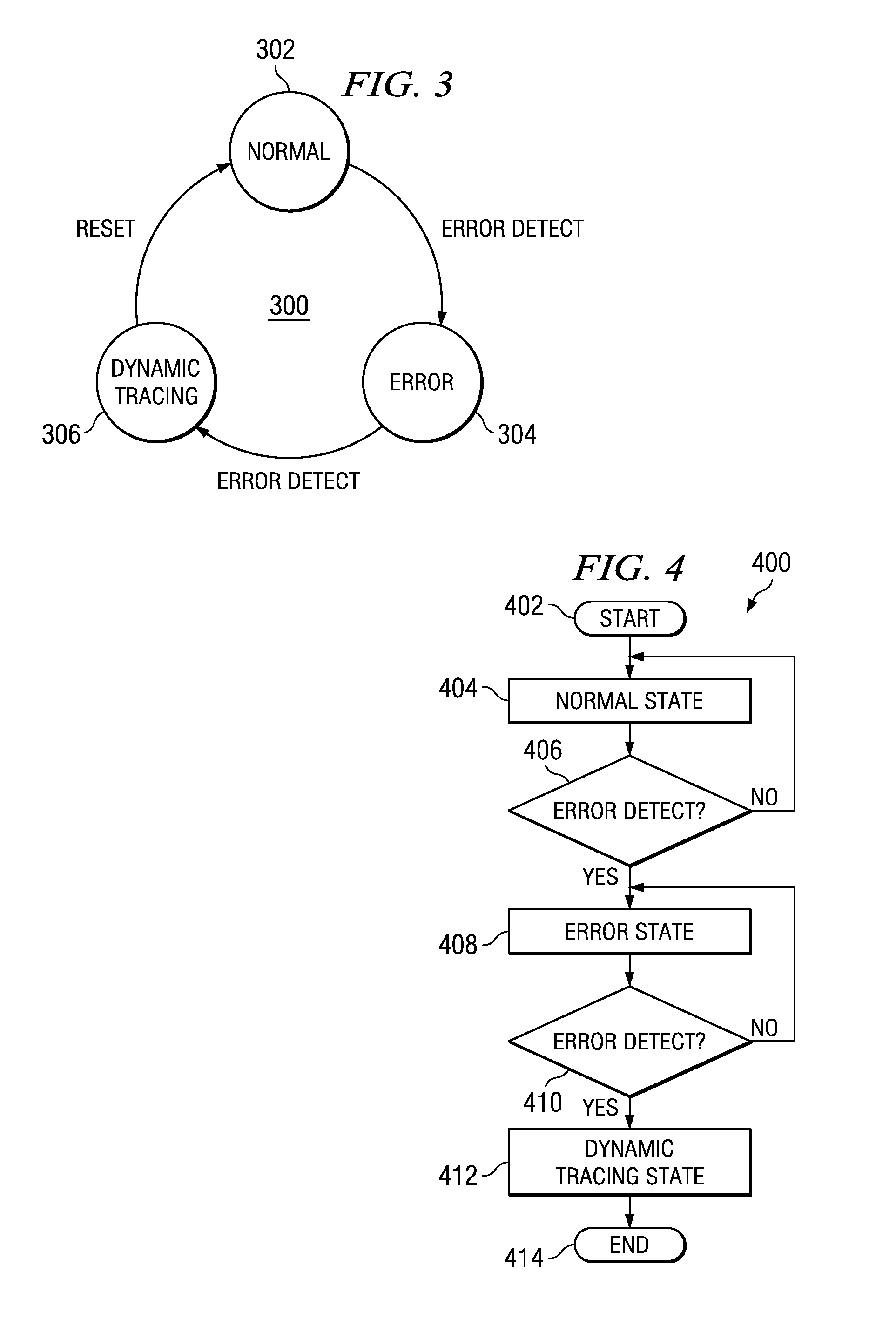
[0009]A computer implemented method, system, and computer usable program code is provided for staged tracing, where an initial high-level trace is performed to detect potential problems or issues at a sub-system level, followed by a dynamic tracing state, with a more detailed level of tracing for an identified problematic sub-system. During such dynamic tracing, the CPU consumption or processing time is monitored, and if such consumption remains below a given threshold, additional trace points may be added. If such CPU consumption exceeds the given threshold, existing trace-points are selectively backed-out or removed. The dynamic adding and removing of trace-points allows for the CPU to perform in a desired window of execution performance such that the overall system performance is not adversely affected when tracing is enabled.

Problems solved by technology

Trace points are not typically enabled on a customer system operating in its normal environment, but rather are generally limited to being used during system debug, due to the adverse effect that tracing can have on system performance.
This is because the tracing activity itself consumes system resources such as processor cycles and data storage latencies.
The tracing can also adversely effect system operation as the sequencing or timing of data processing operations may be different when tracing is enabled due to such system resource consumption by the tracing operation.

Method used


Image

  • Dynamic enablement and customization of tracing information in a data processing system
  • Dynamic enablement and customization of tracing information in a data processing system
  • Dynamic enablement and customization of tracing information in a data processing system

Examples


Embodiment Construction

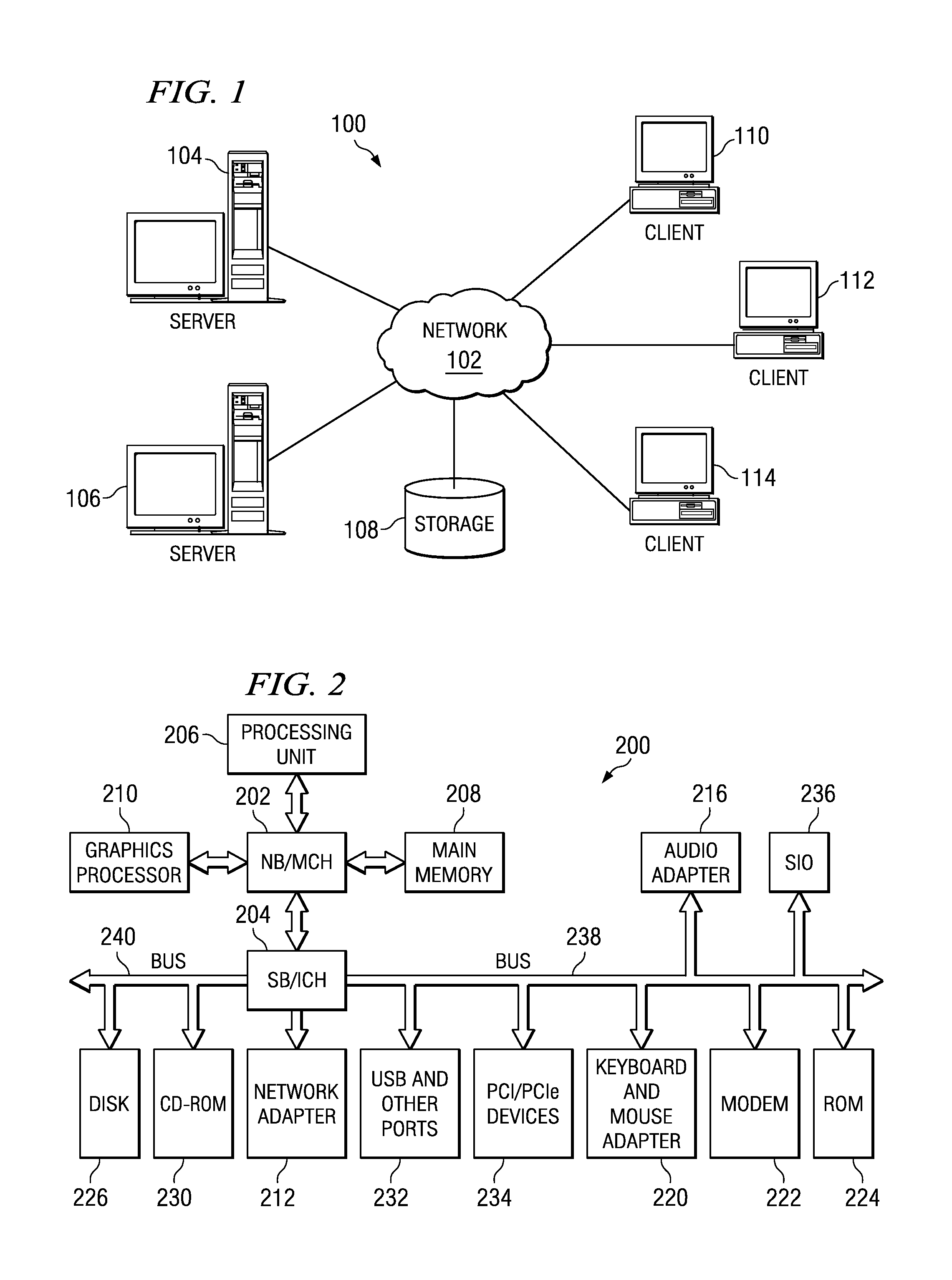
[0019]With reference now to the figures and in particular with reference to FIGS. 1-2, exemplary diagrams of data processing environments are provided in which illustrative embodiments may be implemented. It should be appreciated that FIGS. 1-2 are only exemplary and are not intended to assert or imply any limitation with regard to the environments in which different embodiments may be implemented many modifications to the depicted environments may be made.

[0020]With reference now to the figures, FIG. 1 depicts a pictorial representation of a network of data processing systems in which illustrative embodiments may be implemented. Network data processing system 100 is a network of computers in which embodiments may be implemented. Network data processing system 100 contains network 102, which is the medium used to provide communications links between various devices and computers connected together within network data processing system 100. Network 102 may include connections, such a...


PUM


Abstract

A computer implemented method, system, and computer usable program code for staged tracing, where an initial high-level trace is performed to detect potential problems or issues at a sub-system level, followed by a dynamic tracing state, with a more detailed level of tracing for an identified problematic sub-system. During such dynamic tracing, the CPU consumption or processing time is monitored and if such consumption remains below a given threshold, additional trace points may be added. If such CPU consumption exceeds the given threshold, existing trace-points are selectively backed-out or removed. The dynamic adding and removing of trace-points allows for the CPU to perform in a desired window of execution performance such that the overall system performance is not adversely affected when tracing is enabled.

Description

BACKGROUND OF THE INVENTION[0001]1. Field of the Invention[0002]The technical field is generally related to data processing system tools used to analyze and diagnose a data processing system, and in particular is directed to a computer implemented method, system, and computer usable program code for providing improved tracing of software or code that is executing on such data processing system.[0003]2. Description of the Related Art[0004]Finding problems with computer software, also known as debugging software, can be a daunting task. Certain hardware and software tools currently exist to assist a programmer in such debug activities. A software trace facility helps isolate system problems by monitoring selected system events during code execution. Events that can be monitored include: entry and exit to selected subroutines, kernel routines, kernel extension routines, and interrupt handlers. When the trace facility is active, information about these events is recorded in a system tra...

Claims


Application Information

Patent Timeline
IPC IPC(8): G06F11/28G06F11/07
CPCG06F11/3644
Inventor GIROUARD, JANICE MARIELEWIS, JAMES K.STROSAKER, MICHAEL THOMASVOIGT, WENDEL GLENN
Owner IBM CORP
Learn More