Fixture for analyzing thin flexible electronic device

a thin flexible electronic device and fixing technology, applied in the field of fixing, can solve the problems of panel manufacturer finding out problems with ics, display still needs to be returned to ic vendor for failure analysis, and encounter the problem of return of goods from clients, so as to facilitate failure analysis and reduce the probability of failure

Inactive Publication Date: 2008-05-29
DENMOS TECH
View PDF5 Cites 0 Cited by
  • Summary
  • Abstract
  • Description
  • Claims
  • Application Information

AI Technical Summary

Benefits of technology

[0012]Accordingly, the present invention is directed to a fixture. The fixture is used to analyze a thin flexible electronic device, so as to facilitate the failure analysis, and to reduce the probability of failure during the failure analysis.
[0015]To sum up, the present invention uses a fixture to reduce the time of the failure analysis process and to save more cost. Moreover, the fixture simplifies the wiring lines, so as to prevent unexpected failure due to misconnection of the lines. In addition, the user can adjust the aligning position of the thin flexible electronic device more easily.

Problems solved by technology

However, vendors of driving ICs for displays often encounter the problem of return of goods from clients, which normally happens in the following two situations.
One situation is that after an IC vendor ships the completed chips to a panel manufacturer, the panel manufacturer finds out problems with the ICs during usage.
The other situation is that the panel manufacturer doesn't find out the problems with the ICs until the displays using the ICs are completed and shipped to consumers, and the consumers find out the problems with the driving ICs.
However, in such a situation, the displays still need to be returned to the IC vendor for failure analysis.
However, such a method not only consumes time, but also costs a lot.
1. Pins 101 of the PCB 20 are located above the PCB 20, which not only makes the wiring difficult but also causes misconnection in use due to the disordered wiring.
This may likely cause damage to the TCP 50.
Besides, if the TCP 50 is not aligned properly, and needs to be moved, it is necessary to repeatedly screw and unscrew for removing and fixing, which is very inconvenient to the user.
In view of the above, how to resolve the above problems is an important issue for the IC manufacturers in the field.

Method used


Image

  • Fixture for analyzing thin flexible electronic device
  • Fixture for analyzing thin flexible electronic device
  • Fixture for analyzing thin flexible electronic device

Examples


Embodiment Construction

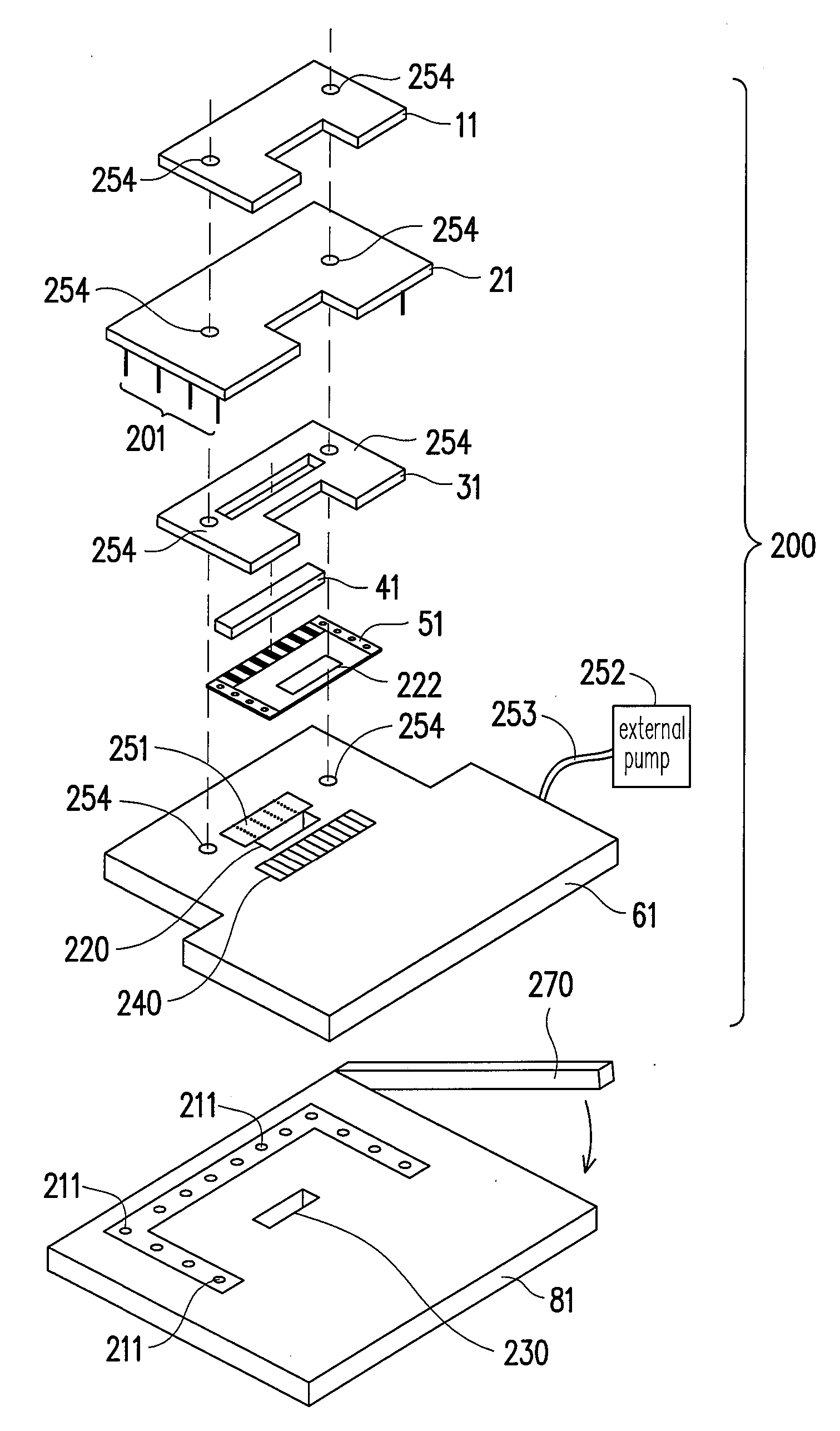
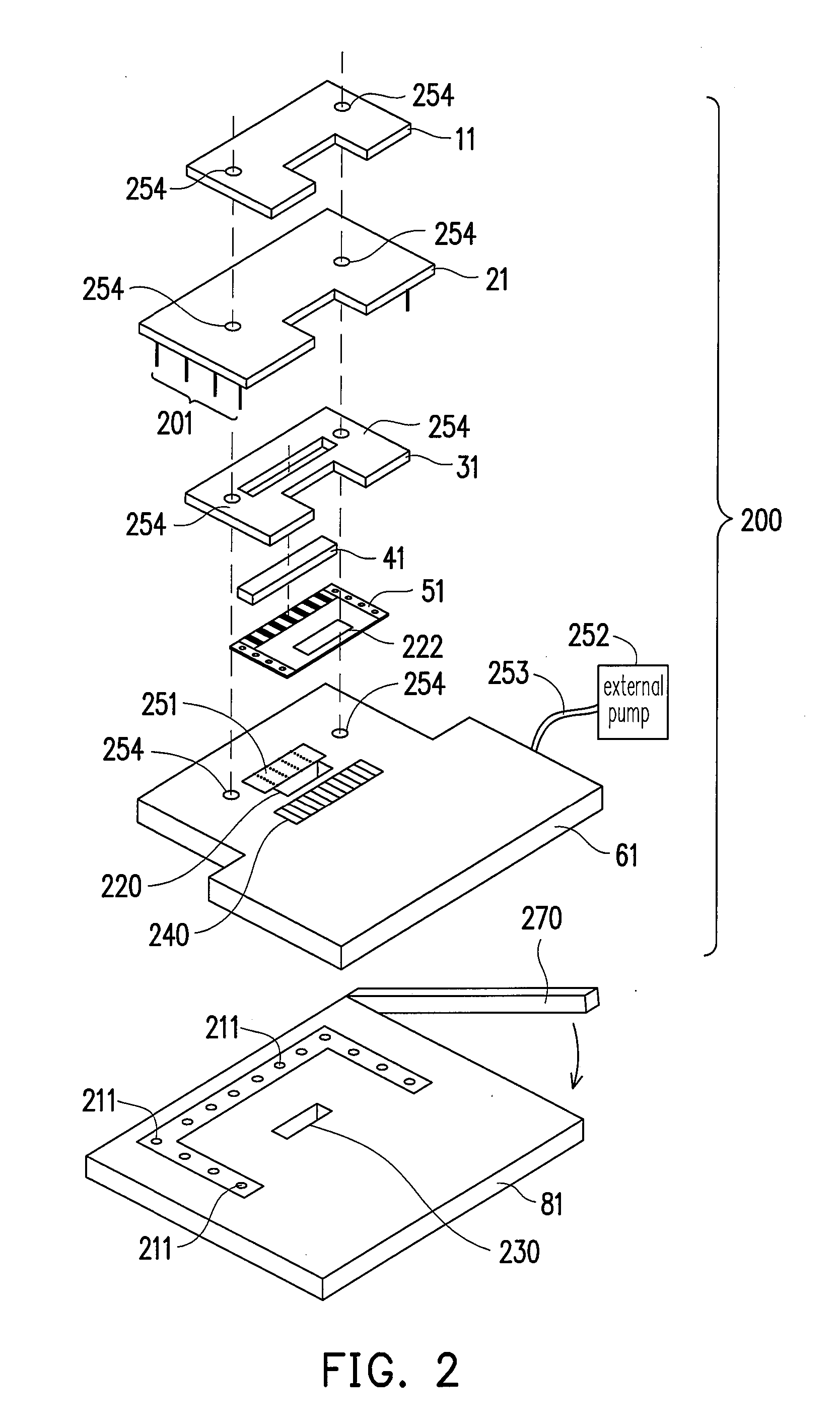
[0021]FIG. 2 is an exploded view of a fixture according to a preferred embodiment of the present invention. Referring to FIG. 2, the fixture 200 includes a top holder 11, a second stage 21, a bottom holder 31, a conductive rubber layer 41, and a first stage 61. The fixture 200 is used for analyzing a thin flexible electronic device 51. In this embodiment, the thin flexible electronic device 51 is comprised of, for example but not limited to, a COF. Alternatively, the thin flexible electronic device 51 can be other forms of packaged chips, for example, the TCP and the like. The top holder 11 of the fixture 200 covers the stage 21 from above, for fixing and protecting the stage 21. The bottom holder 31 is disposed between the stage 61 and the stage 21 for fixation and protection as well. The bottom holder 31 includes a conductive rubber layer 41, through which the stage 21 and the thin flexible electronic device 51 are electrically connected. The electrical connection thereof may be i...


PUM


Abstract

A fixture for facilitating failure analysis of a thin flexible electronic device is provided. The fixture includes a first stage and a second stage. The second stage covers the first stage from above, and the thin flexible electronic device is disposed between the first stage and the second stage. The second stage includes conductive pads, conductive paths, and pins. Positions of the conductive pads correspond to the electrical connection points of the thin flexible electronic device. The pins are disposed under the second stage, and the pins are respectively electrically connected to the conductive pads through the conductive paths.

Description

CROSS-REFERENCE TO RELATED APPLICATION[0001]This application claims the priority benefit of Taiwan application serial no. 95143922, filed Nov. 28, 2006. All disclosure of the Taiwan application is incorporated herein by reference.BACKGROUND OF THE INVENTION[0002]1. Field of the Invention[0003]The present invention relates to a fixture. More particularly, the present invention relates to a fixture for a thin flexible electronic device.[0004]2. Description of Related Art[0005]In the modern days with flourishing science and technology, electronic devices are being designed to be light, thin, short, and small. With the improvement of semiconductor technology, liquid crystal displays with many advantageous features such as low power consumption, thin profile, light weight, high resolution, high color saturation, and long life have been developed, and are being widely used in electronic products used in our everyday life, such as notebook and desktop computers and liquid crystal televisio...

Claims


Application Information

Patent Timeline
Patent Type & Authority Applications(United States)
IPC IPC(8): G01R31/02
CPCG01R1/0408
Inventor CHOU, YI-PINGLAI, YUN-TAI
Owner DENMOS TECH
Why Eureka
Try Eureka