
System and Control Method of Oil Burner's Suitable Burning Ratio Using Air Pressure Sensor

a technology of air pressure sensor and oil burner, which is applied in the direction of burners, fuel supply regulation, combustion regulation, etc., can solve the problems of difficult to control air fuel ratio, abnormal combustion state, and the most important control of air fuel ratio in the oil burner. to achieve the effect of stably controlling the air fuel ratio of the oil burner

Inactive Publication Date: 2008-05-22
KYUNGDONG NETWORK
View PDF9 Cites 8 Cited by
  • Summary
  • Abstract
  • Description
  • Claims
  • Application Information

AI Technical Summary

Benefits of technology

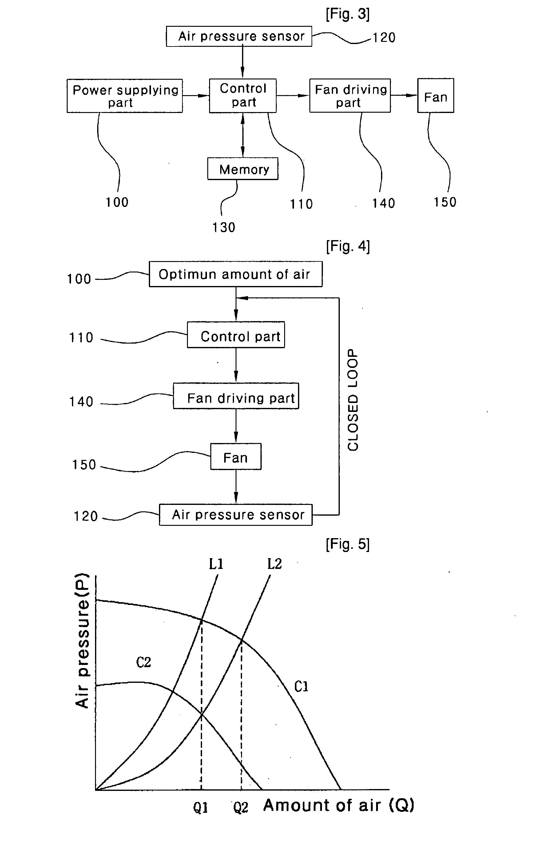
[0019]As described above, although a control system according to the present invention may be subject to external disturbance after the control system has been installed or during the control system is being used, since a fan is proportionally rotated based on a detection signal of an air pressure sensor, it is possible to supply an amount of air suitable for the oil burner.
[0020]Accordingly, it is possible to stably control an air fuel ratio of the oil burner.

Problems solved by technology

Recently, the control of the air fuel ratio in the oil burner becomes the most important issue.
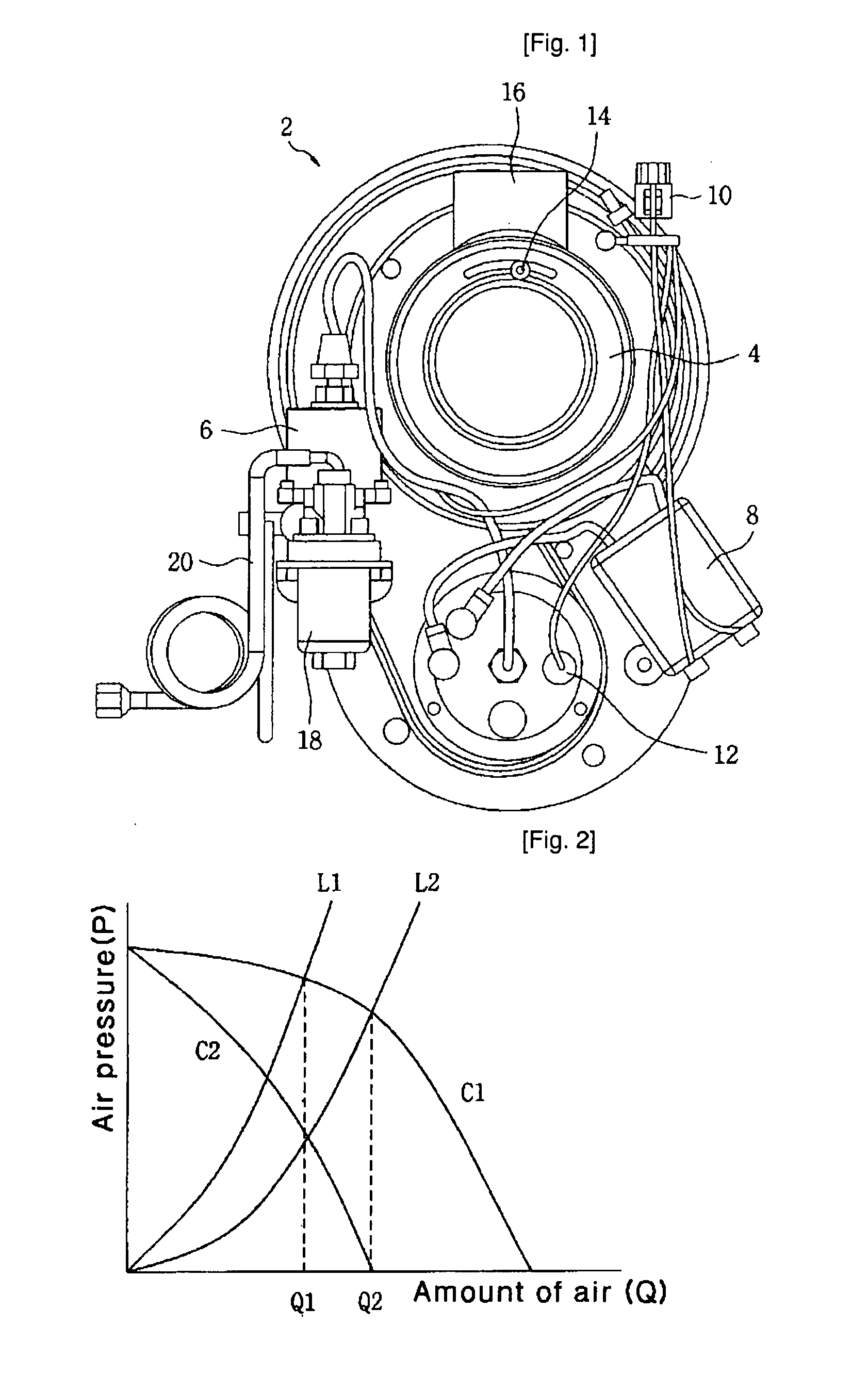
In general, such a damper 14 is regulated when it is manufactured or installed, and it is difficult to actually control an air fuel ratio because the damper 14 is manually regulated.
On the assumption that load of the heat exchanger is L2 when the same burner is employed in another heat exchanger, if the damper 14 is not controlled, an amount of air becomes Q2, so that an amount of air greater than the optimum amount of air is supplied, thereby causing an abnormal combustion state.
First, after installing the oil burner, resistance of an internal flow path of the heat exchanger may be changed due to soot generated when the oil burner is turned on / off.
Second, the resistance of a blower may be changed according to the length of an exhaust funnel if the damper is regulated in a manufacturing process.
Third, the resistance of the blower may frequently be changed due to a wind even if the same exhaust funnel is employed.
As a result, it frequently happens that an amount of air supplied to the oil burner deviates from an optimum amount of air required for combustion of the oil burner, so that the combustion of the oil burner becomes unstable.

Method used


Image

  • System and Control Method of Oil Burner's Suitable Burning Ratio Using Air Pressure Sensor
  • System and Control Method of Oil Burner's Suitable Burning Ratio Using Air Pressure Sensor
  • System and Control Method of Oil Burner's Suitable Burning Ratio Using Air Pressure Sensor

Examples


Embodiment Construction

[0026]Reference will now be made in detail to the preferred embodiments of the present invention.

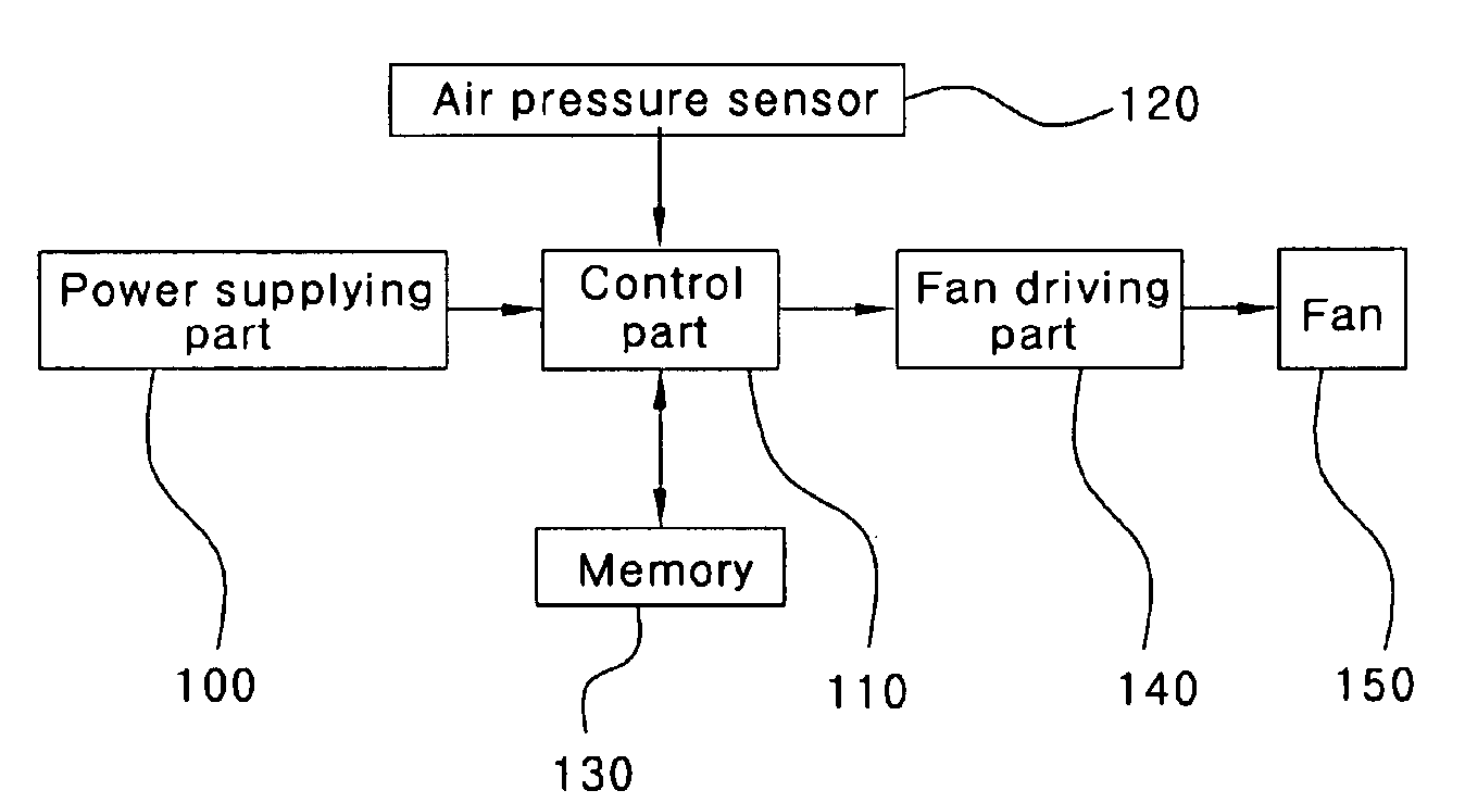
[0027]FIG. 3 is a block diagram illustrating a structure of a system for controlling an air fuel ratio by an air pressure sensor according to the present invention, FIG. 4 is a view illustrating a procedure for controlling an air fuel ratio of an oil burner according to the present invention, and FIG. 5 is a view illustrating a method for regulating an amount of air by changing an RPM of a fan installed in the oil burner according to the present invention.

[0028]Referring to FIG. 3, the system according to the present invention includes a power supplying part 100, which receives electric power, converts the electric power into pre-determined driving voltage, and supplies the driving voltage to the system, a fan 150, which operates as a blower for receiving basic driving power from the power supplying part 100 and then supplying air required for the combustion of the oil burner, a fan driv...


PUM


Abstract

Disclosed are a system and a method for precisely controlling an air fuel ratio of an oil burner, which is extensively used in a household boiler, an industrial boiler, or a heater, using an air pressure sensor. The system includes a power supplying part, a fan for supplying air required for combustion of the oil burner by receiving driving voltage from the power supplying part, a fan driving part serving as a controller which drives the fan, an air pressure sensor, which is installed at a side of a flow path of air supplied from the fan so as to detect an amount of the supplied air, and a control part for outputting an optimum RPM of the fan to the fan driving part by comparing a signal detected by the air pressure sensor with preset data related to an optimum amount of air. The method includes the steps of detecting an amount of air being supplied through a fan using the air pressure sensor, calculating an optimum RPM of the fan using a controller by comparing a signal about the amount of the air with preset data related to an optimum amount of air, outputting the RPM calculated by means of the controller to a fan driving part, and rotating the fan according to the calculated RPM input into the fan driving part.

Description

TECHNICAL FIELD[0001]The present invention relates to a system for controlling an air fuel ratio of an oil burner and a method thereof, and more particularly to a system and a method for precisely controlling an air fuel ratio of an oil burner, which is extensively used in a household boiler, an industrial boiler, or a heater, using an air pressure sensor.BACKGROUND ART[0002]In general, boilers used for heating rooms or halls are classified into an oil boiler, a gas boiler, and an electric boiler according to kinds of fuel supplied to the boilers. The boilers have been variously developed and used corresponding to a size of a room or a hall or their installation purpose. An oil boiler from among such boilers and a heater using oil as fuel thereof include an oil burner.[0003]In particular, it is very important for the oil burner to precisely control an air fuel ratio. Recently, the control of the air fuel ratio in the oil burner becomes the most important issue.[0004]Hereinafter, det...

Claims


Application Information

Patent Timeline
Patent Type & Authority Applications(United States)
IPC IPC(8): F23N1/02
CPCF23D11/001F23N3/02F23N3/082F23N2039/06F23N2023/44F23N2025/06F23N2033/08F23N2023/36F23N2223/36F23N2223/44F23N2225/06F23N2233/08F23N2239/06F24H9/20
Inventor MIN, TAE-SIK
Owner KYUNGDONG NETWORK
Learn More