
Front structure for car body

a front structure and car body technology, applied in the direction of roofs, bumpers, vehicular safety arrangments, etc., can solve the problems of not having sufficient stiffness for high-speed collisions, and not agreeing with the intention of effectively absorbing striking energy at a limited space, so as to reduce time and cost. , the effect of reducing the time and cos

Inactive Publication Date: 2008-05-22
HYUNDAI MOTOR CO LTD
View PDF2 Cites 37 Cited by
  • Summary
  • Abstract
  • Description
  • Claims
  • Application Information

AI Technical Summary

Benefits of technology

[0008]Embodiments of the present invention provide a front structure for a car body to minimize time and cost to repair a car body after a collision by localizing damage in low-speed collisions to a crash box mounted in a space between a front bumper and a side member and making the car body deform always in a predetermined mode in the collisions.

Problems solved by technology

Because crash boxes in the related art had to be designed with low stiffness to effectively absorb striking energy at low-speed collisions, not only they could not have sufficient stiffness for high-speed collisions, but also deformation due to a collision was not localized to the crash boxes and progresses to the front side member.
However, since the increase of the closed cross section, thickness, and length for crash boxes in the related art is an important matter that changes the whole external shape of the front of a car body, it does not agree with an intention that is to effectively absorb striking energy at a limited space.

Method used


Image

  • Front structure for car body
  • Front structure for car body
  • Front structure for car body

Examples


Embodiment Construction

[0014]Hereinafter, a detailed description will be given of the present invention.

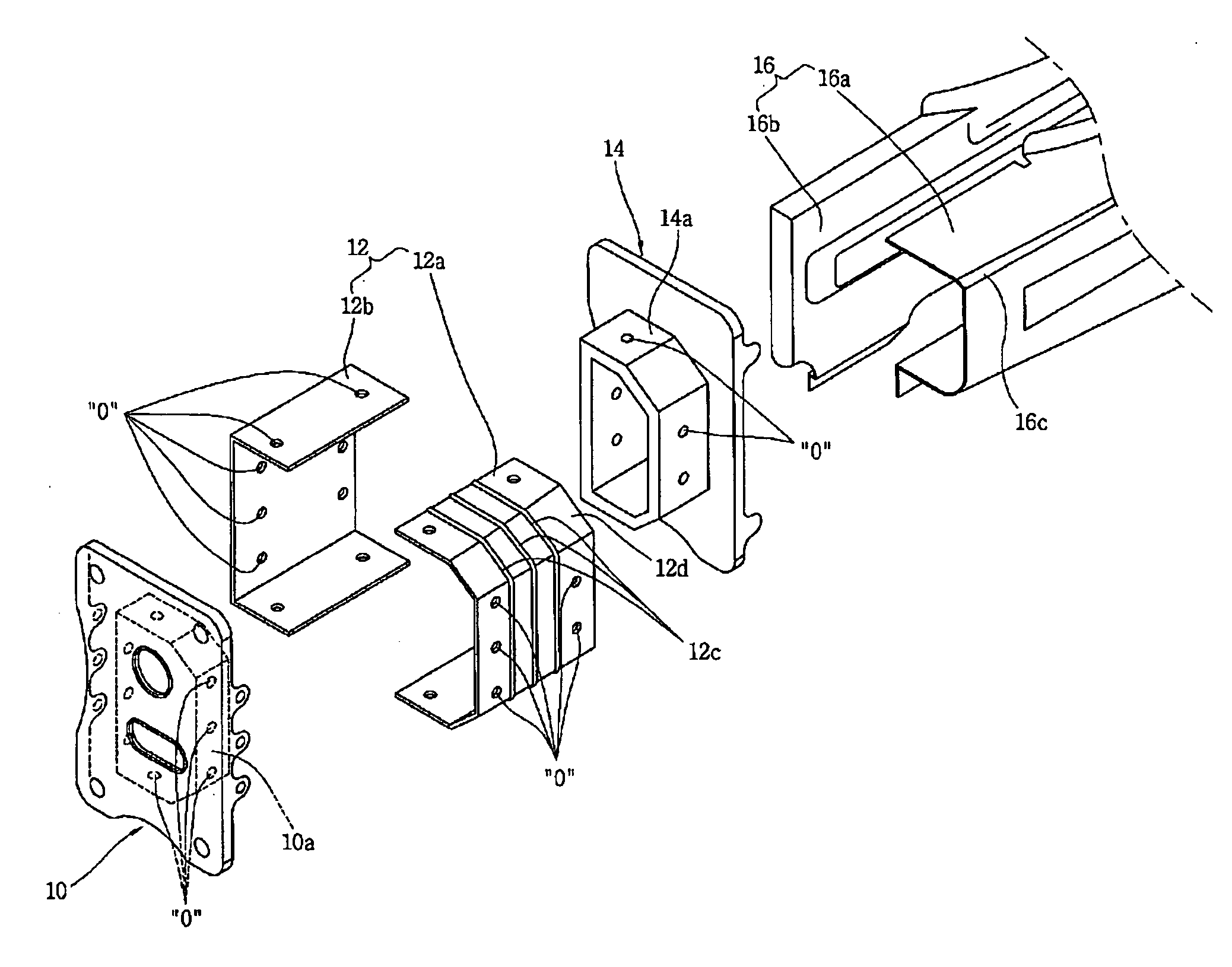
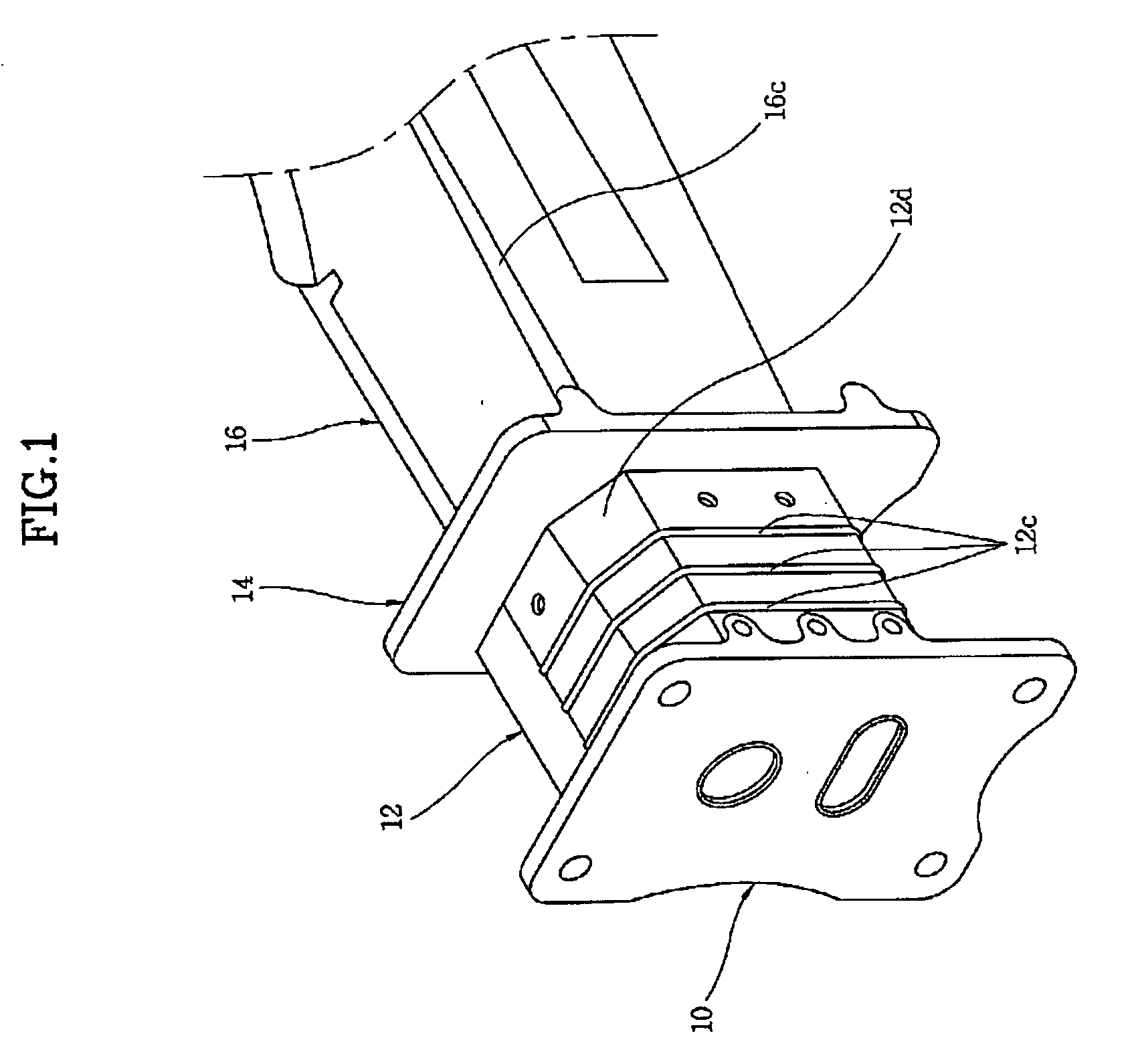
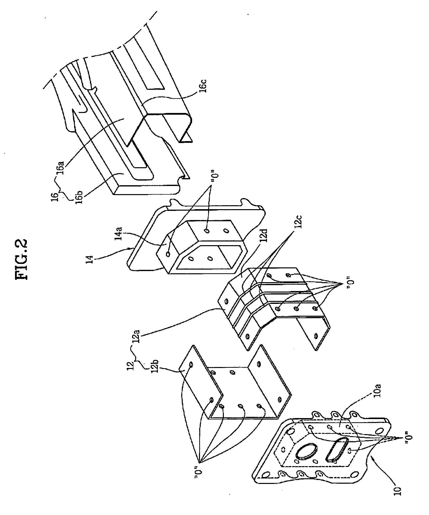
[0015]As shown in FIG. 1, a front structure for a car body includes an first connecting bracket 10 supporting the rear of a front bumper (not shown) at the left and right front ends of the front bumper, a crash box 12 detachably joined to the rear of first connecting bracket 10, a second connecting bracket 14 detachably joined to the rear of crash box 12, and a front side member 16 joined to the rear of second connecting bracket 14.

[0016]Crash box 12 includes an inner member 12a and outer member 12b, which are curved and separated from each other, so as to extend in the longitudinal direction of the vehicle and have a closed cross section. Inner member 12a has a plurality of bead-shaped protrusions 12c formed across it and longitudinally spaced from each other. Inner member 12a and outer member 12b are joined by welding, with upper and lower portions overlapped, and form a closed cross-sectional space h...


PUM


Abstract

A front structure for a car body that reduces time and cost to repair a car body after a collision by localizing damage in low-speed collisions to a crash box mounted in a space between a front bumper and a side member and making the car body deform always in a predetermined mode in the collisions. A front structure for a car body may include a first connecting bracket supporting the left and right rear of a front bumper, a crash box joined to the rear of the first connecting bracket, a second connecting bracket joined to the rear of the crash box, and a front side member joined to the rear of the second connecting bracket. The crash box includes an inner member and an outer member, which are curved and separated from each other, so as to extend in the longitudinal direction of the vehicle and have a closed cross section. The inner member has a plurality of bead-shaped protrusions that are formed across the inner member and longitudinally spaced from each other.

Description

CROSS-REFERENCE TO RELATED APPLICATIONS[0001]The present application is based on, and claims priority from, Korean Application Serial Number 10-2006-0115169, filed on Nov. 21, 2006, the disclosure of which is hereby incorporated by reference herein in its entirety.FIELD OF THE INVENTION[0002]The present invention relates to a front structure for a car body and, more particularly, to a front structure including a crash box that is mounted in a space between a front bumper and front side member and absorbs striking energy to reduce damage of a vehicle in low-speed collisions.BACKGROUND OF THE INVENTION[0003]Manufacturers of vehicles have made significant investments in improving safety in recent years, that is, much effort has been made to reduce loss due to damage of vehicle and injury of passengers, particularly in preparation for a collision.[0004]For example, collisions of vehicles are largely classified into a high-speed collision above 40 km / h and a low-speed collision below 15 ...

Claims


Application Information

Patent Timeline
Patent Type & Authority Applications(United States)
IPC IPC(8): B60R27/00B60R99/00
CPCB60R19/34B60R19/24B60R19/023B60R19/04B60R2019/1886B60R2019/247B60R2019/026
Inventor BAE, KI-SOON
Owner HYUNDAI MOTOR CO LTD
Learn More