
Switch unit operable with rocker switches for control units

a control unit and switch technology, applied in the field of switch units, can solve problems such as uneven alignment errors, dislocations and dislocations of region, and bonded tapes no longer fulfilling their tolerance-reducing function

Inactive Publication Date: 2008-05-22
VISTEON GLOBAL TECH INC
View PDF4 Cites 9 Cited by
  • Summary
  • Abstract
  • Description
  • Claims
  • Application Information

AI Technical Summary

Problems solved by technology

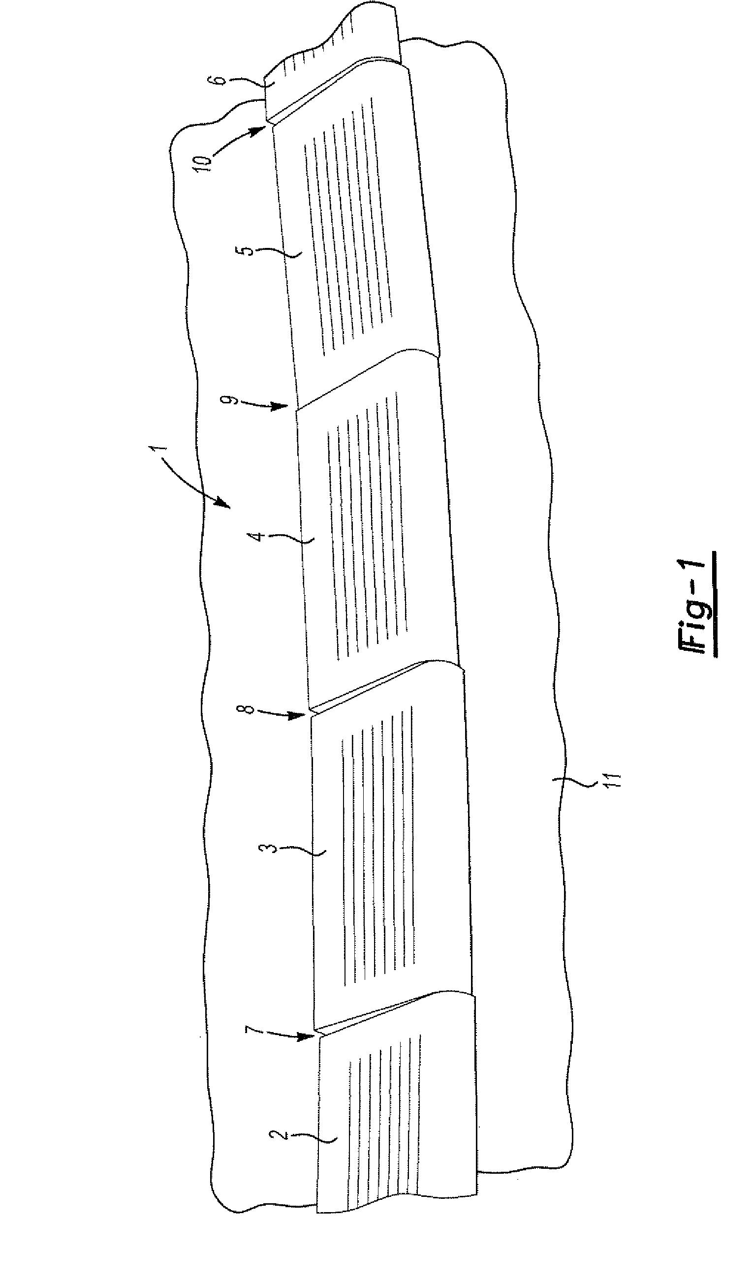
A problem is that there are dis-placements and dislocations which distort the region, occurring as errors of alignment 7, 8, 9, 10 between the individual neighbouring push-button caps 2, 3, 4, 5, 6 of the rocker switches, these errors caused by the structure of the compact units, which are placed behind the control panel, of the rocker switches.
A problem is that due to the large number of tolerances brought in within the compact unit, already there the causes of the errors of alignment 7, 8, 9, 10 are present so that the push-button caps are not aligned correctly along the given region of the control panel, which is noticed even more, if neighboring push-button caps have different shapes.
In addition, the errors of alignment may be not always uniform, of the same magnitude, but different from push-button cap to push-button cap.
So it is just a matter of time that the bonded tapes no longer fulfill their tolerance-reducing function.
The other problem of traditional controls with rocker switches is that the metal leaf spring in the compact unit influences the actuation force in such a way that the motion-force diagrams of the upward and downward directions are different.
A problem of both known arrangements of switching elements is that the circuit boards are located with the switching elements parallel to the surface of the push-button caps.

Method used


Image

  • Switch unit operable with rocker switches for control units
  • Switch unit operable with rocker switches for control units
  • Switch unit operable with rocker switches for control units

Examples


Embodiment Construction

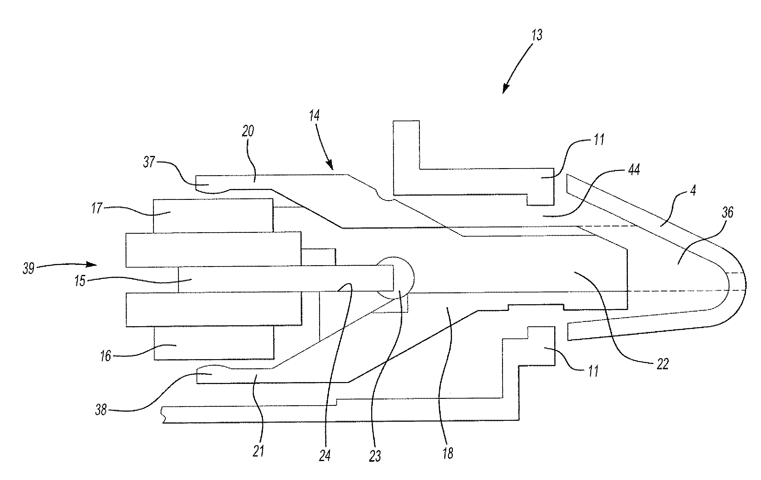
[0026]It is the objective of the invention to disclose a switch unit operable with help of rocker switches for control units, the switch unit established such that errors of alignment between the push-button caps of the rocker switches at the control panel are largely avoided. Further, it is intended to reduce the component expenditure in the compact units assigned to the rocker switches.

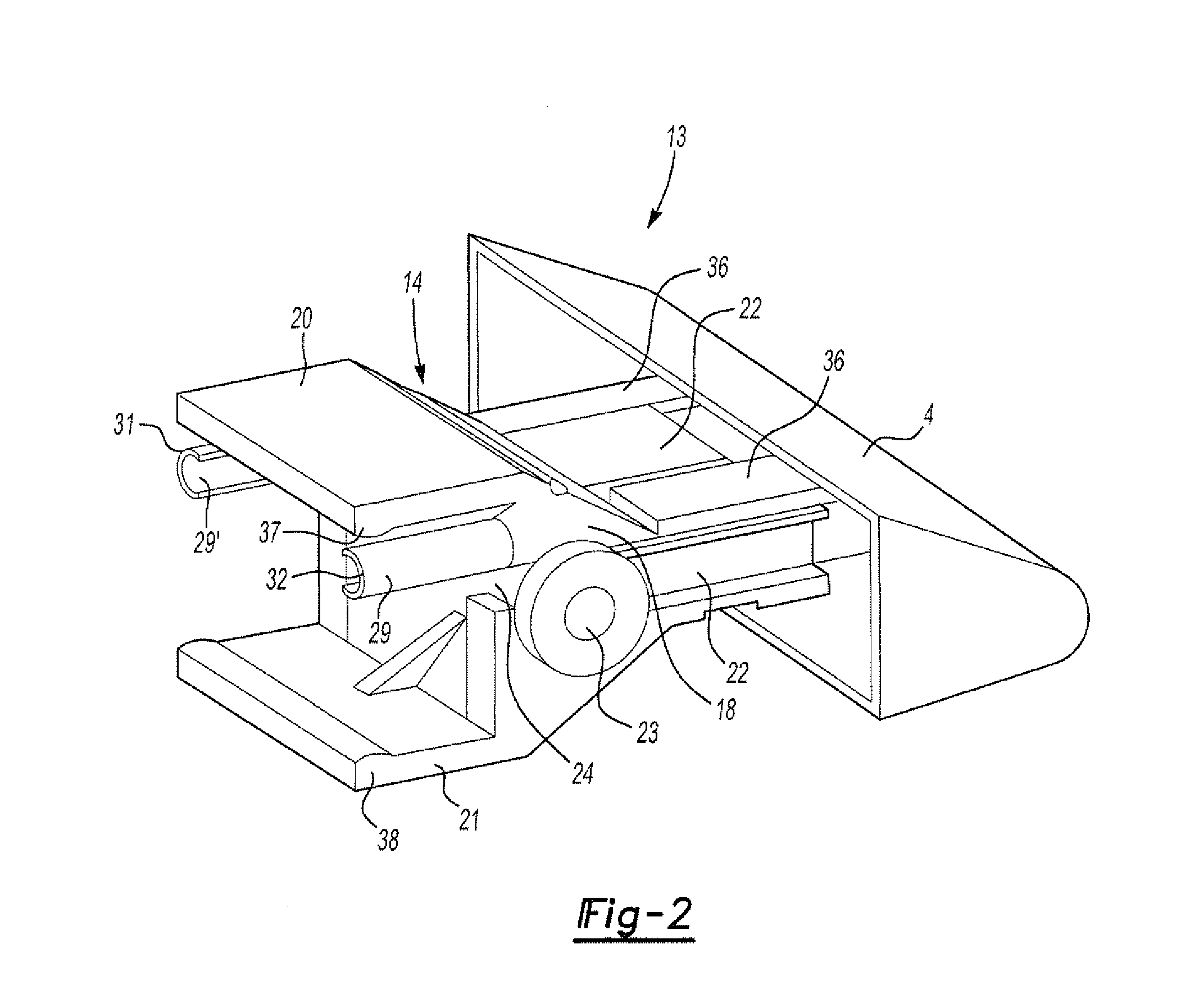
[0027]The problem of the prior art is solved by the features of claim 1. The switch unit is operable with help of rocker switches for control units is provided with a compact unit for actuating electrical contacts on circuit boards by moving push-button switches by means of push-button caps, which are connected each to a swiveling lever pivoted in a rotary bearing, the swiveling lever applying mechanical pressure contact to the push-button switch by rocking a push-button cap, the compact unit according to the characterizing part of claim 1 including a fixed part with a circuit board and a push-butto...


PUM


Abstract

A switch unit operable with help of rocker switches for control units is disclosed herein. The switch unit is provided with a compact unit for actuating electrical contacts on circuit boards by moving push-button switches by means of push-button caps. The caps are each connected to a swiveling lever which is pivoted in a rotary bearing. Each of the swiveling levers applies mechanical pressure contact to the respective push-button switch when the respective push-button cap is rocked. The compact unit is provided with a fixed part having a circuit board. Each of the push-button switches is located sandwich-like, above and below the circuit board. The circuit board is also inserted into a groove of the rotary bearing. The compact unit is also provided with guiding parts, each itself provided with a guiding forming and a leaf spring in each guiding forming. The compact unit is also provided with a moving part in the form of the swiveling lever pivotable about the rotary bearing. The swiveling lever is divided into two tongue parts spreading V-shaped opposite to the respective push-button cap. Each of the two tongue parts extends towards an associated push-button switch. Both of the guiding formings and the leaf springs cooperate to bias the swiveling lever to an original position.

Description

BACKGROUND OF THE INVENTION[0001]1. Field of the Invention[0002]The invention relates to a switch unit operatable with help of rocker switches for control units provided with a compact unit for actuating contacts on circuit boards by moving push-button switches by means of push-button caps, which are connected each to a swiveling lever pivoted in a rotary bearing, the swiveling lever applying mechanical pressure contact to the push-button switch by rocking a push-button cap.[0003]2. Description of Related Prior Art[0004]Traditional switch units 1 attached at control panels 11, such as the switch unit shown in FIG. 1 in a perspective front view, particularly for HVAC controls in vehicles, are provided with several rocker switches which are equipped with neighbouring push-button caps 2, 3, 4, 5, 6 aligned along a given region of the control panel. A problem is that there are dis-placements and dislocations which distort the region, occurring as errors of alignment 7, 8, 9, 10 between ...

Claims


Application Information

Patent Timeline
Patent Type & Authority Applications(United States)
IPC IPC(8): H01H3/00B60K35/10
CPCB60K37/06H01H23/006H01H2229/064H01H23/30H01H2221/044H01H23/146B60K35/10
Inventor STRABER, BRITTABURMEISTER, STEFANRODE, ANDREAS
Owner VISTEON GLOBAL TECH INC
Learn More