
Pump with torque reversal avoidance feature and engine system using same

a technology of torque reversal and engine system, which is applied in the direction of piston pumps, positive displacement liquid engines, pump parameters, etc., can solve the problems of undesirable noise, undesirable wear and tear on the gear train, and undesirable torque reversal on the pump's cam shaft, etc., and achieves positive torque

Inactive Publication Date: 2008-05-22
CATERPILLAR INC
View PDF17 Cites 14 Cited by
  • Summary
  • Abstract
  • Description
  • Claims
  • Application Information

AI Technical Summary

Benefits of technology

[0008]In another aspect, an engine system includes an engine housing that includes an exhaust passage. A fuel system includes a pump with a high pressure outlet in fluid communication with a common rail, which is in fluid communication with a plurality of fuel injectors. An exhaust aftertreatment system is in fluid communication with the exhaust passage, and includes a fuel dispenser in fluid communication with

Problems solved by technology

Because of the relatively high pressures involved, the force on the back side of the cam as the retraction stroke of the pump piston begins can potentially lead to undesirable torque reversals on the pump's cam shaft.
Because these types of high pressure common rail fuel pumps are often driven by a gear train coupled to an engine's crank shaft, a torque reversal can briefly relieve tooth pressure contact in the gear train, which can lead to undesirable noise when the teeth of the gear train reengage when the torque on the cam shaft again becomes positive.
The noise produced in the gear train from torque reversals can lead to undesirable wear and tear on the gear train, but more importantly lead to excessive noise.
Although these references teach strategies that may avoid torque reversals in some pumping configurations, asymmetrical cam shapes are not always an option, and arranging the pump pistons at different angular locations around the cam shaft may also not be an available design option in many instances.
Apart from torque reversal issues associated with a high pressure common rail fuel pump, many engine systems also include other auxiliary pump requirements that must be met.

Method used


Image

  • Pump with torque reversal avoidance feature and engine system using same
  • Pump with torque reversal avoidance feature and engine system using same
  • Pump with torque reversal avoidance feature and engine system using same

Examples


Embodiment Construction

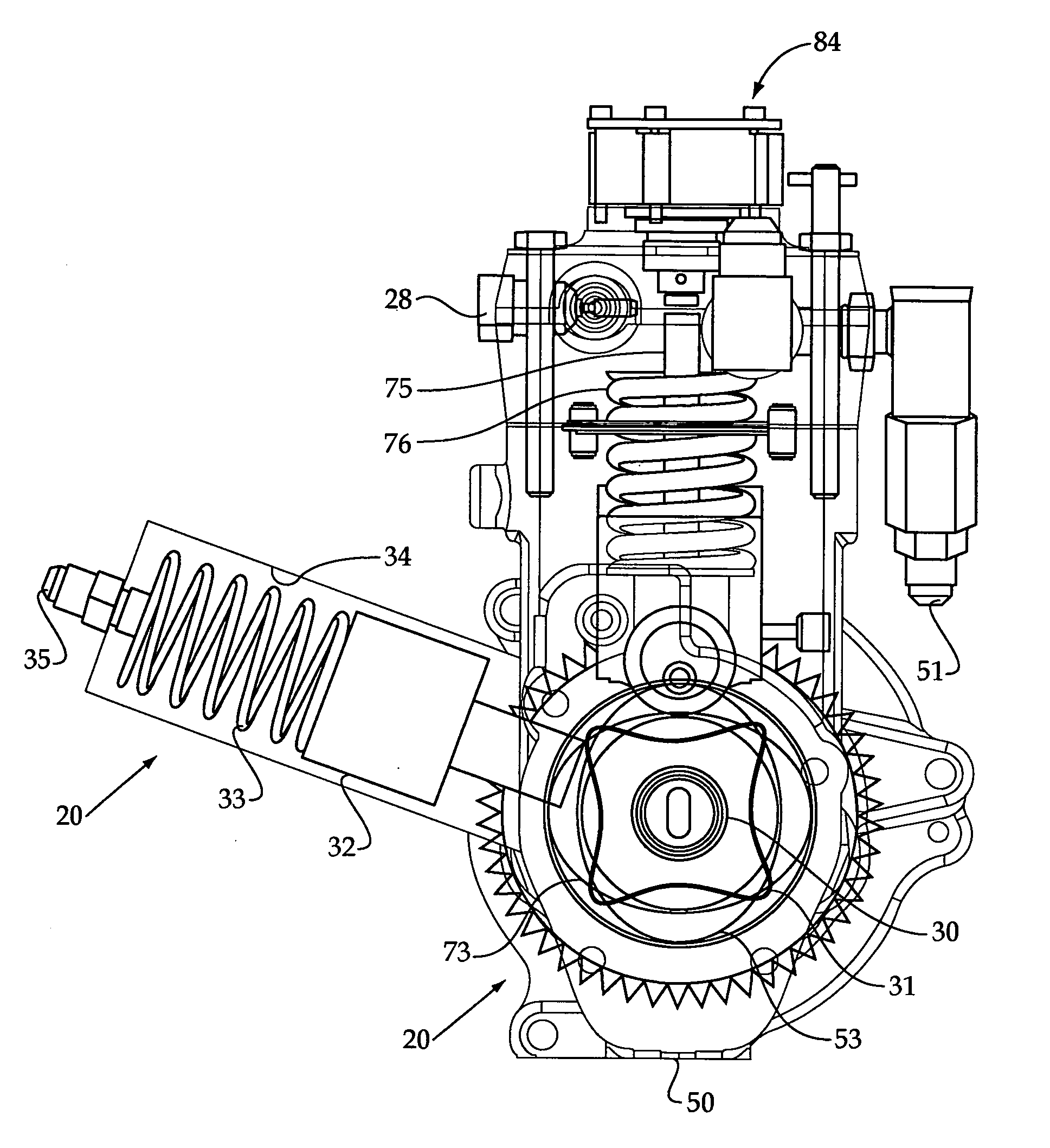
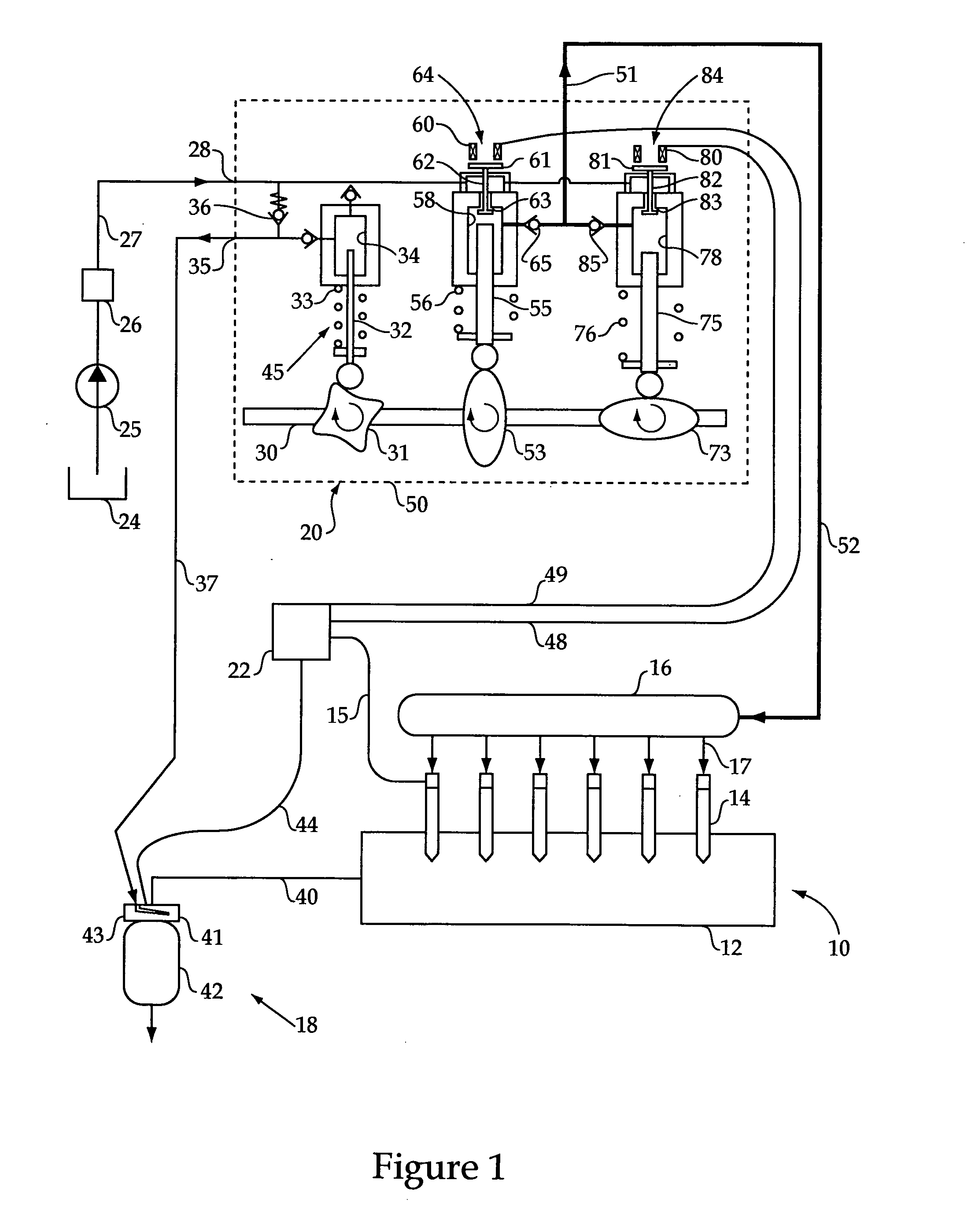
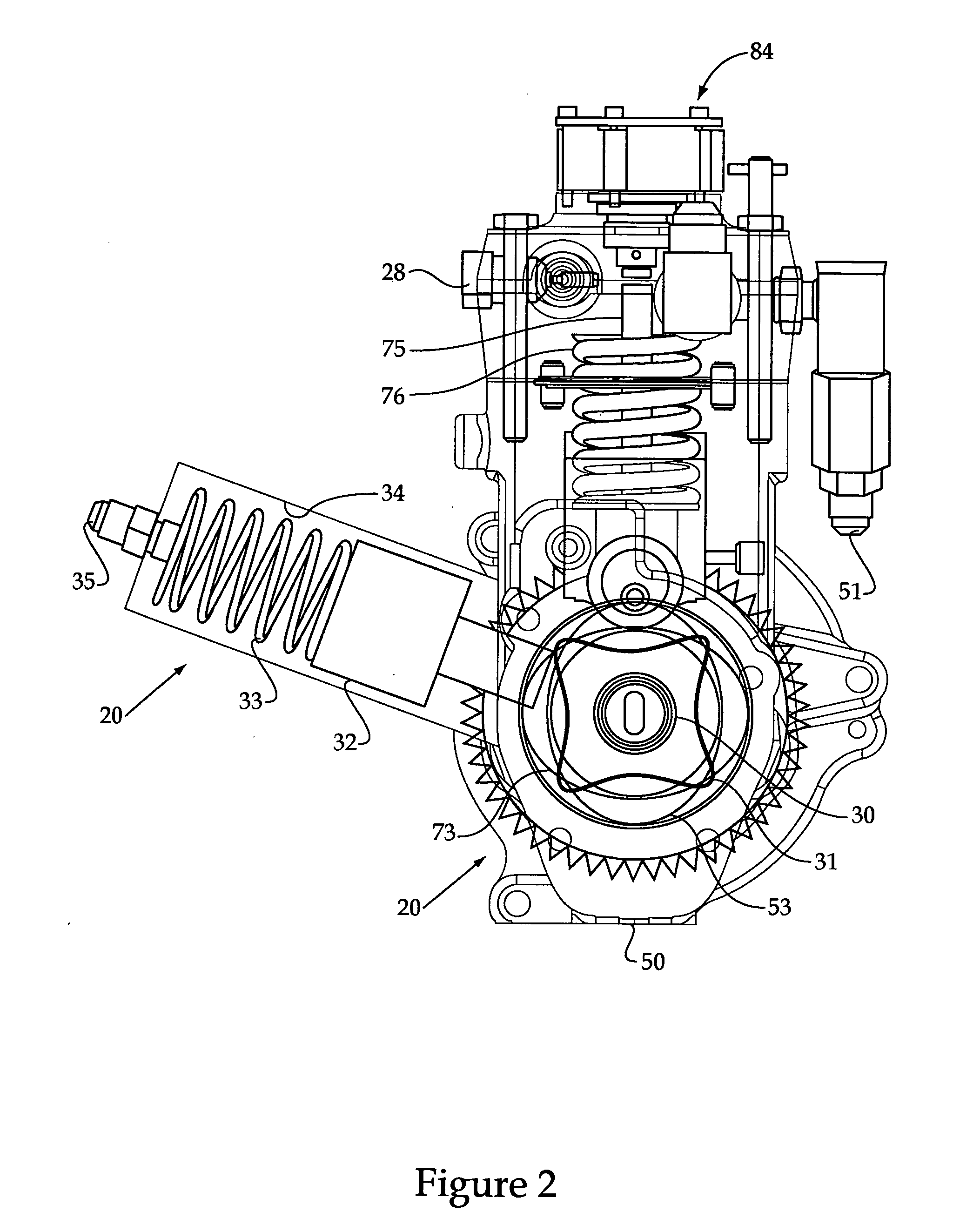
[0013]Referring to FIGS. 1 and 2, an engine system 10 includes an engine housing 12 with a plurality of fuel injectors 14 mounted therein. In particular, the illustrated embodiment shows an engine 10 with six fuel injectors 14 positioned for direct injection of liquid fuel into six separate combustion chambers. Thus, the illustrated embodiment shows a six cylinder compression ignition engine. However, those skilled in the art will appreciate that the teachings of the present disclosure are applicable to engines with more or less cylinders, and also to engines having other ignition strategies, such as spark ignition, etc. Although not necessary, fuel injectors 14 may be electronically controlled via individual communication lines 15 (only one shown) that are in communication with an electronic controller 22 in a conventional manner. Thus, electronic controller 22, with appropriate signals, controls both fuel injection timing and quantity in a manner well known in the art. In this exa...


PUM


Abstract

A high pressure pump for a common rail fuel system avoids torque reversals in its cam shaft by applying a cyclic parasitic load. As the high pressure pump pistons transition from a pumping stroke to a retraction stroke, the cyclic parasitic loading device is loaded to avoid torque reversals in the cam shaft. The cyclic parasitic load device may include a medium pressure pump, such as for supplying medium pressure fuel to a particle trap regeneration device associated with the exhaust after treatment system.

Description

TECHNICAL FIELD [0001]The present disclosure relates generally to avoiding torque reversals in pumps, and more particularly to applying a cyclic parasitic load to a high pressure fuel pump to avoid torque reversals.BACKGROUND [0002]Common rail fuel systems typically utilize one or more high pressure pumps that include one or more high pressure pump pistons to supply fuel to the common rail. In addition, many of these pumps include control features, either through inlet metering or spill control, to control pressure in the common rail. This pressure control aspect is generally accomplished by controlling the volume of fluid displaced to the high pressure common rail with each reciprocation of each high pressure pump piston. In the case of an inlet metered pump, this is accomplished by restricting flow into the pumping chamber so that only the amount of fluid which will maintain the common rail at a desired pressure is allowed to enter the pumping chamber. In the case of a spill contr...

Claims


Application Information

Patent Timeline
IPC IPC(8): F02M37/06F04B17/05F04B35/01
CPCF01N2610/02F02M59/102F02M63/0225F04B2201/1202F04B9/042F04B17/05F02M2200/02
Inventor MERCHANT, JACK A.
Owner CATERPILLAR INC
Learn More