
Device For Patterning Workpieces

a technology for workpieces and workpieces, applied in the direction of decoration arts, printing, other printing apparatuses, etc., can solve the problems of distorted printed images and smudged printing images

Active Publication Date: 2008-05-08
HOMAG HOLZBEARBEITUNGSSYST
View PDF46 Cites 19 Cited by
  • Summary
  • Abstract
  • Description
  • Claims
  • Application Information

AI Technical Summary

Benefits of technology

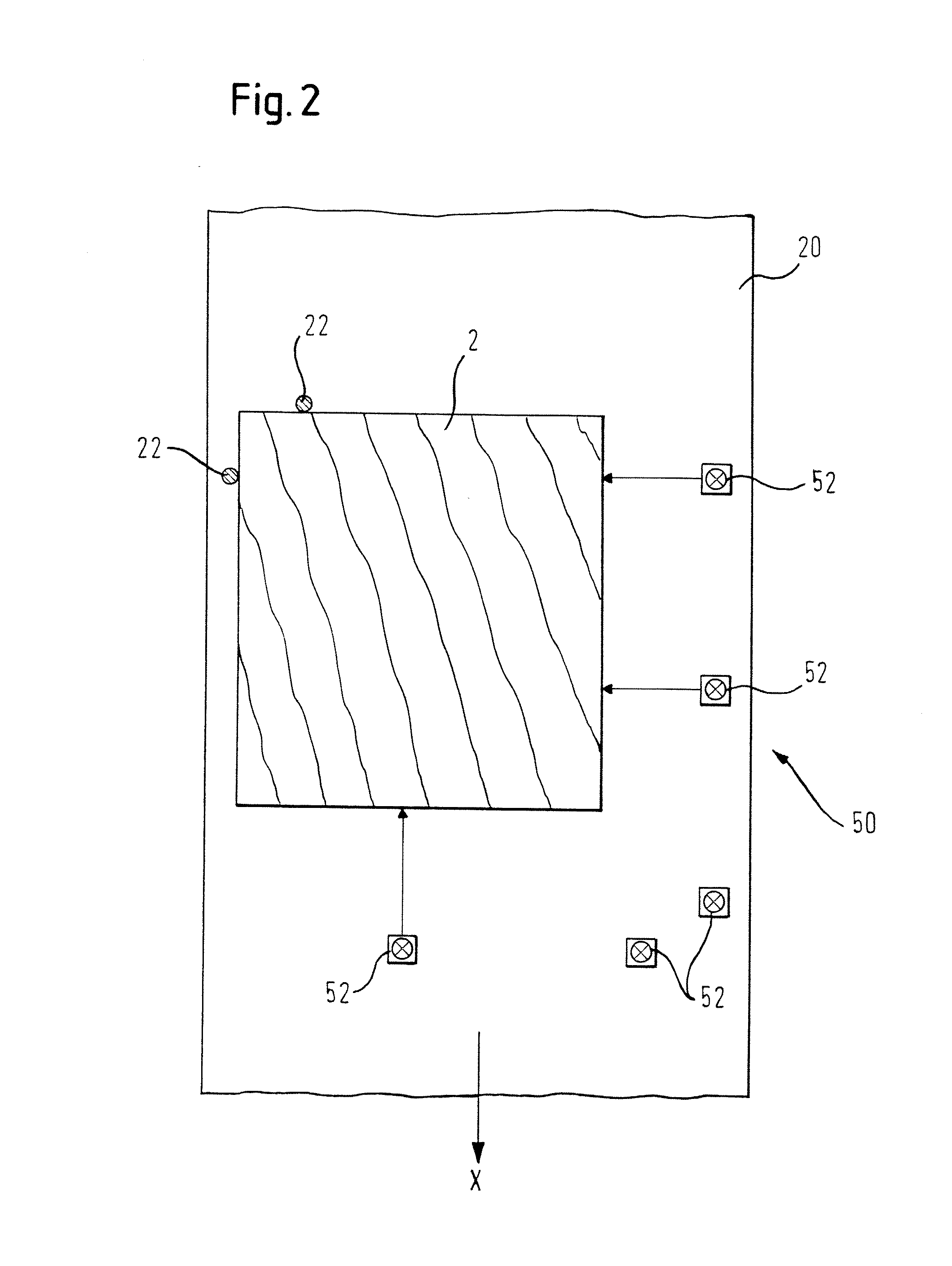
[0006]The underlying idea of the invention is that of basing the printing process, by targeted preprocessing and / or postprocessing, on completely new information. For this purpose, provision is made for the device according to the invention also to have at least one image detection sensor. The provision of at least one image detection sensor opens up entirely new possibilities for controlling and optimising the printing process. It is thus possible, for example, to determine using the image detection sensor the precise position of the workpiece relative to the printing means even before the printing process (“preprocessing”). This allows distortion and smudging of the printed image, which are caused by inadequate relative positioning, to be avoided or minimised. An “overspray”, i.e. printing being carried out beyond a free edge of the workpiece and ink mist being deposited on an adjacent surface of the workpiece, can also be effectively prevented.
[0008]These and further possible applications of the image detection sensor allow the quality of the printed image to be greatly increased over the prior art. The term “image detection sensor” refers in this case at least to any means which operates on an optical basis and supplies information about the image formed (which may or may not be visible to the human eye), so use may be made of a broad range of means including, for example, spectrophotometers with or without (RGB) filters.
[0009]In order to be able efficiently to implement the above-described and further possible applications of the image detection sensor to improve the quality of the printed image, a development of the invention provides for the device further to have a control means which is connected to the at least one image detection sensor and the ink-jet printing means.
[0013]The above-described advantages of the device according to the invention can be achieved particularly advantageously by a method for patterning workpieces according to claim 7. It is in this case particularly preferred that the actual image data obtained through the image detection is compared with desired image data, in particular with regard to the colour spectrum and / or defects and / or geometry and / or colour space (for example, RGB colour space). This desired / actual data comparison can advantageously be utilised as a basis for improving the print quality, for example through the measures described hereinbefore.
[0014]A development of the invention provides in this case for the control signals issued by the control means to the printing means to be corrected on the basis of the desired / actual data comparison in order to minimise deviation between the desired / actual data. The control means thus ensures, on the basis of the image detection performed by the image detection sensor, that the printed image which is actually produced approximates the desired printed image as closely as possible, i.e. optimum printed image quality is achieved.

Problems solved by technology

Nevertheless, it has been found that the workpieces imprinted using a device of this type often have a distorted, smudged printed image or else a printed image displaying defects and colour variations.

Method used


Image

  • Device For Patterning Workpieces
  • Device For Patterning Workpieces
  • Device For Patterning Workpieces

Examples


Embodiment Construction

[0024]Preferred embodiments of the present invention will be described hereinafter in detail with reference to the accompanying drawings.

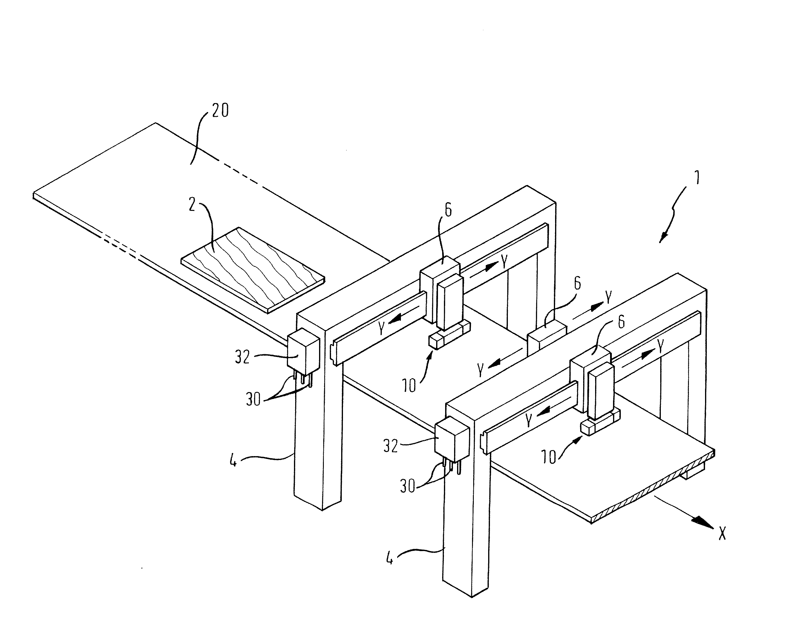
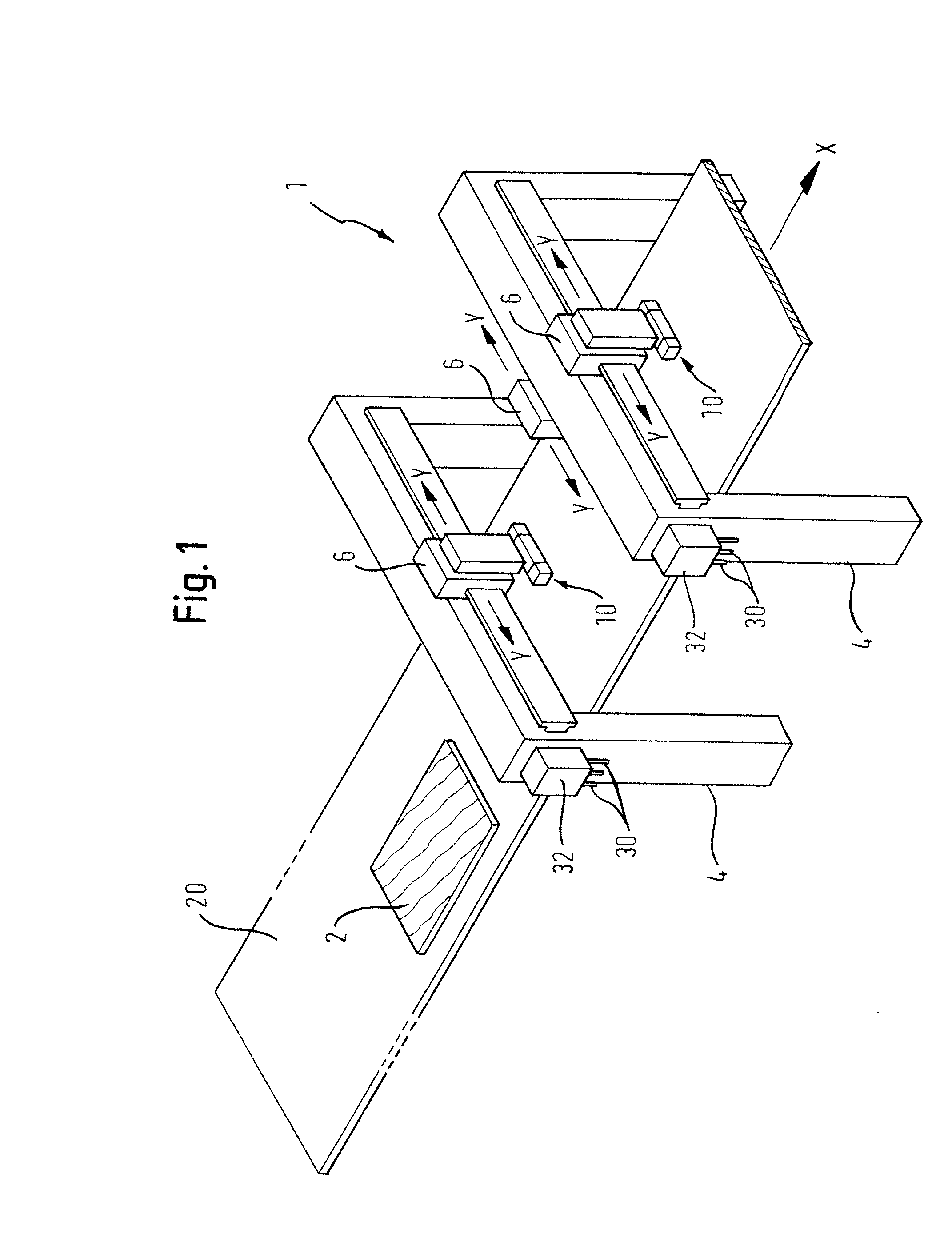
[0025]FIG. 1 is a schematic perspective view of a device 1 for patterning workpieces 2 as a preferred embodiment of the present invention. The device is used for patterning and, if appropriate, machining workpieces 2 which, in the present embodiment, consist at least partially of wood, wood materials, plastics materials or the like, such as are frequently used in the field of furniture and kitchen design.

[0026]The device 1 comprises an ink-jet printing means 10 which, in the present embodiment, operates in accordance with the drop-on-demand principle. As may be seen most clearly in FIG. 4, the ink-jet printing means 10 comprises a plurality of nozzles 12 from which drops of ink can be expelled and which, in the present embodiment, are disposed in a plurality of rows, each row being provided for expelling a predetermined colour, for example the colo...


PUM


Abstract

The invention relates to a device (1) for patterning workpieces (2), which preferably consist at least partially of wood, wood materials or the like, having an ink-jet printing means (10) having a plurality of nozzles (12) from which drops of ink can be expelled, a workpiece carrier means (20) for carrying the workpiece (2) to be patterned, a conveyor device for bringing about a relative movement between the workpiece (2) to be patterned and the printing means (10). The device according to the invention is characterised in that it further has at least one image detection sensor (46).

Description

TECHNICAL FIELD[0001]The invention relates to a device for patterning workpieces, which preferably consist at least partially of wood, wood materials or the like, according to the preamble of claim 1.PRIOR ART[0002]A device of the type mentioned at the outset is known, for example, from DE 100 31 030 B4 and has sensors for roughly detecting the contour and thickness of the workpieces to be imprinted which are attached to a conveyor device or to a portal. Nevertheless, it has been found that the workpieces imprinted using a device of this type often have a distorted, smudged printed image or else a printed image displaying defects and colour variations.[0003]Furthermore, European patent application EP 05 009 326.9, which was filed by the Applicant and has not yet been published, also relates to a device according to the preamble of claim 1.PRESENTATION OF THE INVENTION[0004]The object of the present invention is therefore to provide a generic device for patterning workpieces that all...

Claims


Application Information

Patent Timeline
IPC IPC(8): B41J29/393B41J29/38B41J3/01
CPCB41J2/2139B41J2/2142B41J3/407B44C5/043B41J29/02B41J29/393B41J3/44
Inventor ALBRECHT, LUDWIGFREY, KARLGAUSS, ACHIM
Owner HOMAG HOLZBEARBEITUNGSSYST
Learn More