
Scuba tank cart

a tank cart and tank technology, applied in the field of diving equipment, can solve the problems of bulky flotation device, and high cost of engine providing compressed air

Inactive Publication Date: 2008-05-08
DE LA PRESILLA CESAR +1
View PDF18 Cites 3 Cited by
  • Summary
  • Abstract
  • Description
  • Claims
  • Application Information

AI Technical Summary

Benefits of technology

[0009]These and other features of the present invention will become readily apparent upon further review of the following specification and drawings.

Problems solved by technology

Problems with the use of these devices include the bulk and weight and expense of the engine providing the compressed air.
Additional problems include the bulk of the flotation device used in keeping the air compressor “high and dry” while floating in the water.

Method used


Image

  • Scuba tank cart
  • Scuba tank cart
  • Scuba tank cart

Examples


Embodiment Construction

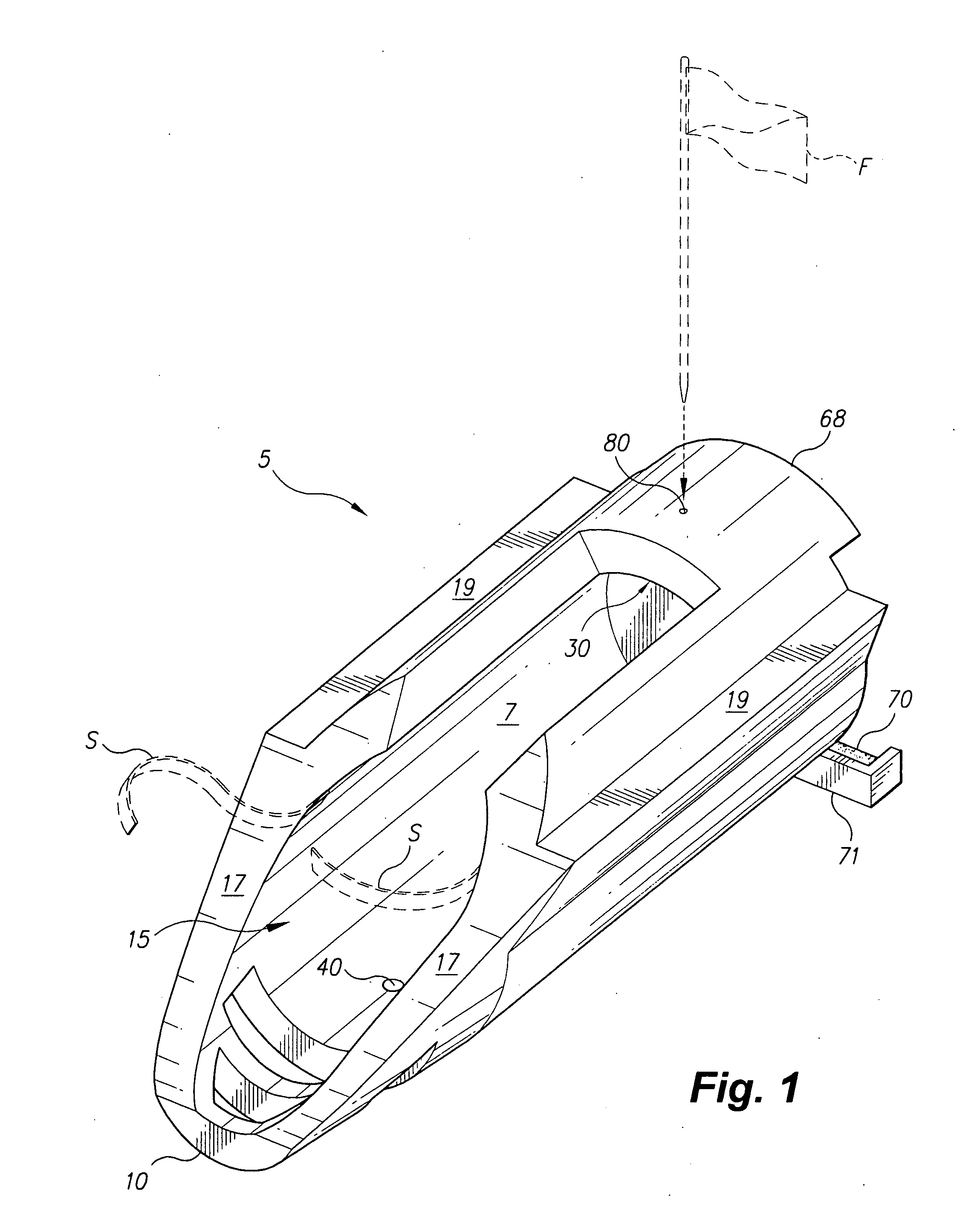
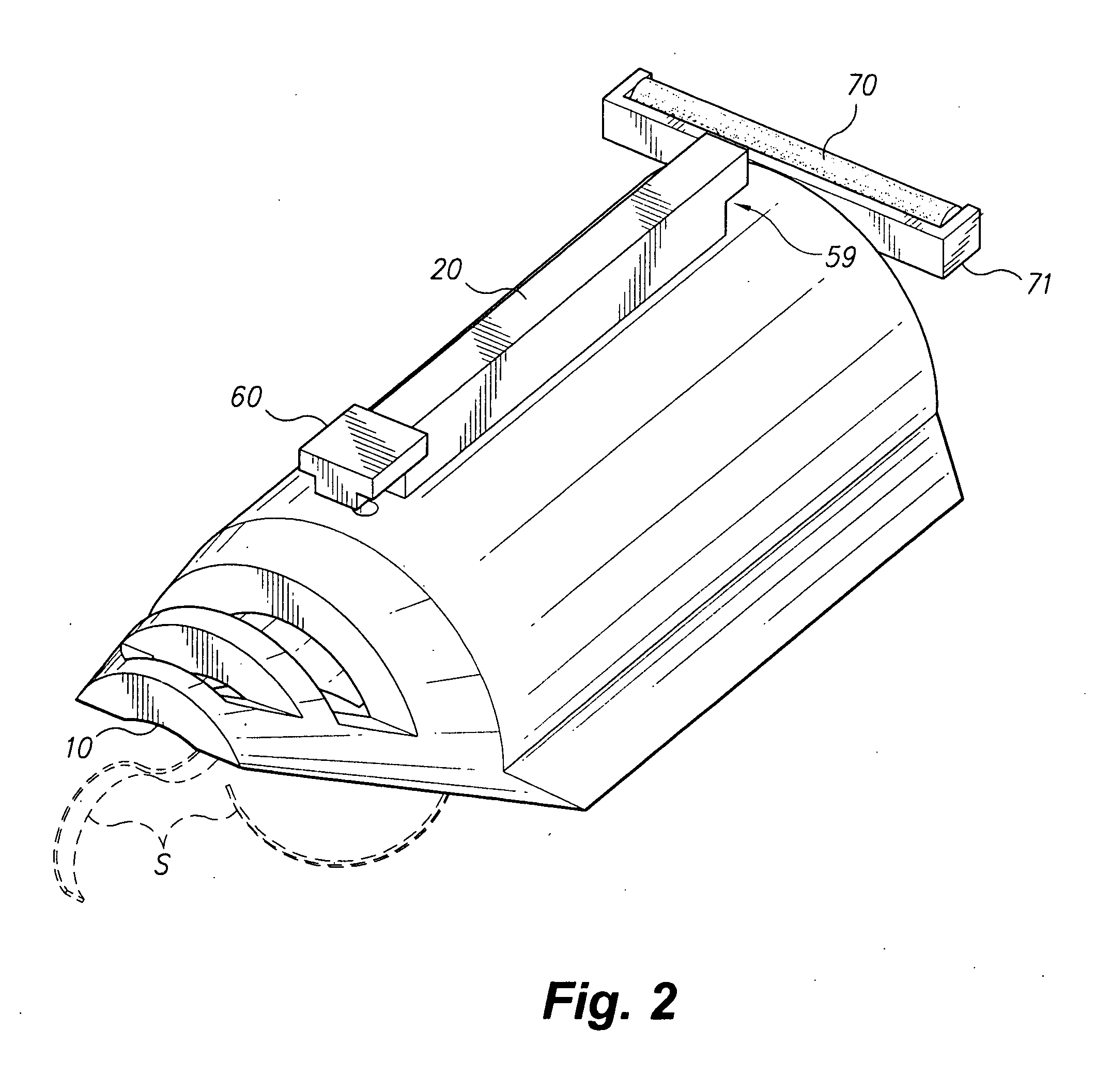
[0017]As shown in FIGS. 1 and 3, the present invention is a scuba tank cart 5 that provides a means of storing a scuba tank T, transporting the tank, and using the apparatus as a tank flotation device in a body of water for diving and snorkeling (scuba is a word now in common parlance that developed from the acronym for Self Contained Underwater Breathing Apparatus). The cart 5 may be made of any seaworthy material, such as a lightweight polymer, metal, fiberglass, or the like. The cart 5 has a roller 70, a body that defines a cavity 15 to fit the scuba tank T, and a rack 20 to store a hose and regulator. As shown in FIGS. 2, 4, 5, and 6, the rack 20 is comprised of an elongate member that extends upward from a location proximate the bottom 400 of the cart 5. The bottom portion of the rack 20 has a recess defined between the elongate member and the body of the cart 5 for winding the hose around the rack 20. The top portion of the rack 20 has a T shaped member 60 for securing the hos...


PUM


Abstract

The scuba tank cart is a scuba transporting apparatus that provides a device for storing a scuba tank, transporting the tank, and using the apparatus as a tank flotation device for diving and snorkeling. The cart has a roller, a cavity to fit a scuba tank, and a bracket to store a hose and regulator. The cart is designed so that when the cart is in the water, the cart floats horizontally to support the tank above the water while the user is underwater carrying only the hose for breathing.

Description

CROSS-REFERENCE TO RELATED APPLICATION[0001]This application claims the benefit of U.S. Provisional Patent Application Ser. No. 60 / 856,305, filed Nov. 3, 2006.BACKGROUND OF THE INVENTION[0002]1. Field of the Invention[0003]The present invention relates to diving equipment for underwater swimming, and more specifically to a scuba tank cart having the capability to float a scuba tank while a user dives underwater carrying only the breathing hose.[0004]2. Description of the Related Art[0005]In some forms of underwater diving or swimming, a compressor carried on a boat or floated upon the water provides air to underwater breathing rigs. Generally powered by electric, diesel or gas, these devices can provide a diver or group of divers the required compressed air to successfully complete a dive without carrying a tank. Problems with the use of these devices include the bulk and weight and expense of the engine providing the compressed air.[0006]Additional problems include the bulk of the ...

Claims


Application Information

Patent Timeline
Patent Type & Authority Applications(United States)
IPC IPC(8): B62B1/18
CPCB62B1/008B62B1/14B62B1/264B63C2011/025B62B2203/44B63C11/20B63C11/26B62B2202/022
Inventor DE LA PRESILLA, CESARSCHMIDT, MICHAEL C.
Owner DE LA PRESILLA CESAR
Learn More