Sailboat Rudder

a technology for sailing boats and rudders, which is applied in the field of rudder systems for sailing boats, can solve the problems of affecting the sailing performance of the sailboat, requiring significant strength and attention, and the design of the rudder is problematic, so as to prevent damage to the rudder and facilitate the movement of the rudder

Inactive Publication Date: 2008-05-08
SANTARONE JOEL F
View PDF11 Cites 5 Cited by
  • Summary
  • Abstract
  • Description
  • Claims
  • Application Information

AI Technical Summary

Benefits of technology

[0008] The preferred rudder system is designed to be pivotally mounted upon the transom of a vessel and provides a mechanism wherein the rudder may be raised to a secured position or lowered to an employed “steering” position as desired by the boater. The rudder may pivot greater than 90 degrees, and preferably approximately 180 degrees, between the steering position and secured position. The invented mechanism for raising and lowering the rudder may be called a “one-pull” system. A single pull of an uphaul line, such as a cord or cable, may be effective in raising the rudder to the secured position, and a single pull of the same uphaul line may be effective in lowering the rudder to the steering position. A pneumatic / gas cylinder or “strut” may be used to dampen the rudder movement between the steering and secured positions, may assist in raising and lowering the rudder, and may help retain the rudder in the desired position once the rudder has been raised or lowered.
[0011] To facilitate movement of the rudder from a secured, upright position to a lowered, “employed” or “steering” position, a cable and pulley system and gas cylinder are provided in the preferred embodiment wherein the boater may accomplish the desired movement using just one pull (for each of the lowering and the raising functions) and preferably just one hand. When the rudder is in the lowered, steering position, should the rudder inadvertently strike an underwater object, the aforementioned system allows rotational movement of the rudder sufficient to clear said underwater object, thereby preventing damage to the rudder, the preferred gas cylinder system provides a bias that returns the rudder to the employed position when the rudder is free from the underwater object.

Problems solved by technology

This type of design is problematic for a number of reasons.
The first reason being that the rudders are usually heavy and require significant strength and attention from the operator or crew of the sailboat to retract the rudder.
Retracting the rudder may distract the operator or crew of the boat from other important duties or events occurring in the craft.
A second reason that a conventional retractable rudder is problematic is that once the rudder is retracted it must be tied off or cleated so that it remains in the retracted position and does not drop back into the water.
Cleating a retractable rudder takes additional time, effort, and attention of the operator or crew of the boat.
Additionally, if a rudder is cleated and an urgent need for control of the craft arises, it takes a significant amount of time and effort to release the rudder back into the water.
However, this design may be problematic if the rudder is held by a friction mounting.
This takes time and strength that may be needed in the craft.
Additionally, if the rudder is stuck in an elevated position above or at the surface of the water the sailboat will have little or no control.
A second problem may arise if the rudder is extended to the rearward from the transom or stern of the craft.
If the rudder strikes an object or control of the boat is attempted with the rudder extended horizontally on the surface of the water, the force exerted on the rudder mounting may be great enough to tear the mounting from the transom of the sailboat or cause the tiller arm to fracture.
Either of these events may cause catastrophic consequences because of loss of control of the sailboat.

Method used


Image

  • Sailboat Rudder
  • Sailboat Rudder
  • Sailboat Rudder

Examples


Embodiment Construction

[0020] While the invention is susceptible of various modifications and alternative constructions, certain illustrated embodiments thereof have been shown in the drawings and will be described below in detail. It should be understood, however, that there is no intention to limit the invention to the specific form disclosed, but, on the contrary, the invention is to cover all modifications, alternative constructions, and equivalents falling within the spirit and scope of the invention as defined in the claims.

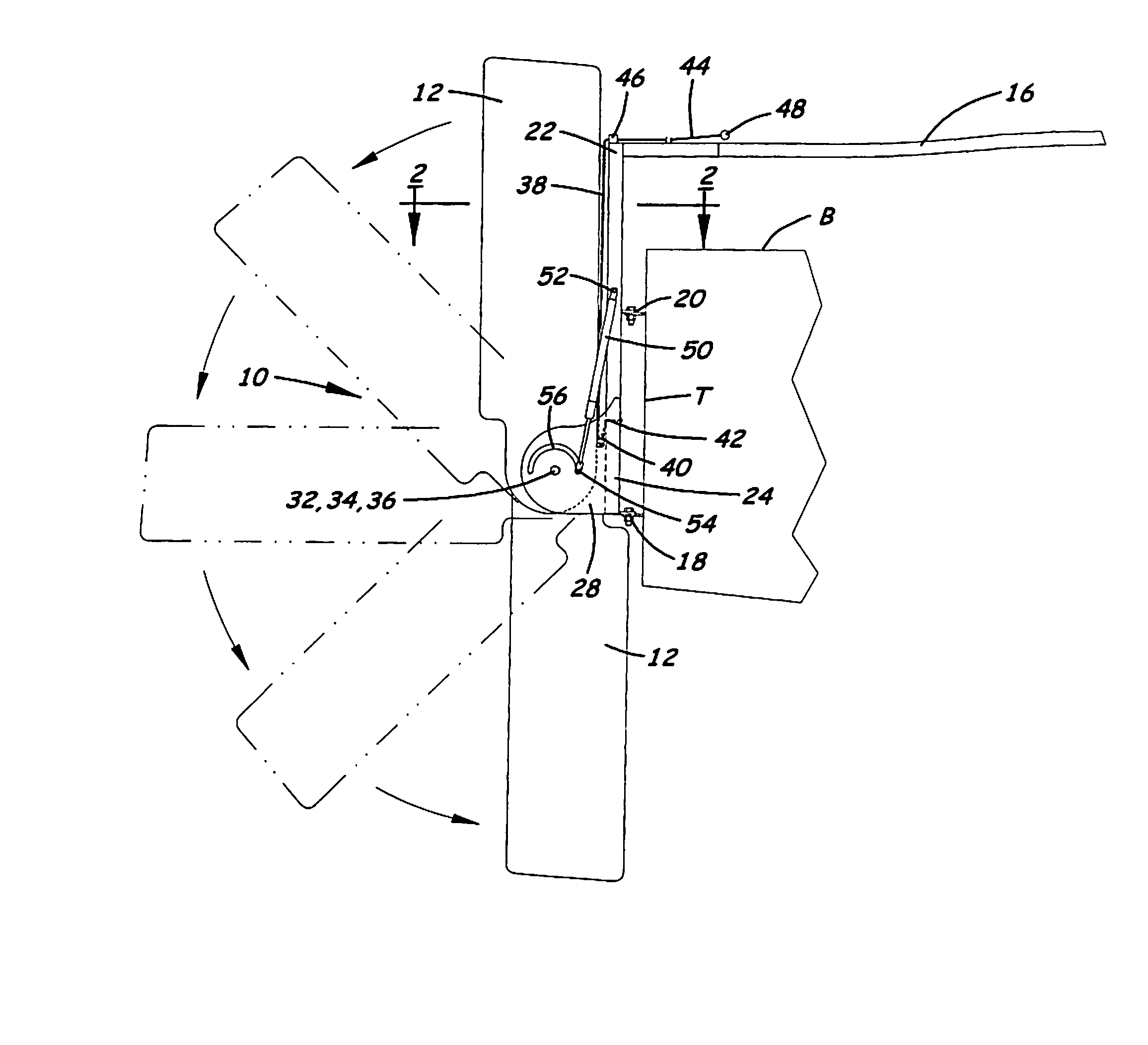
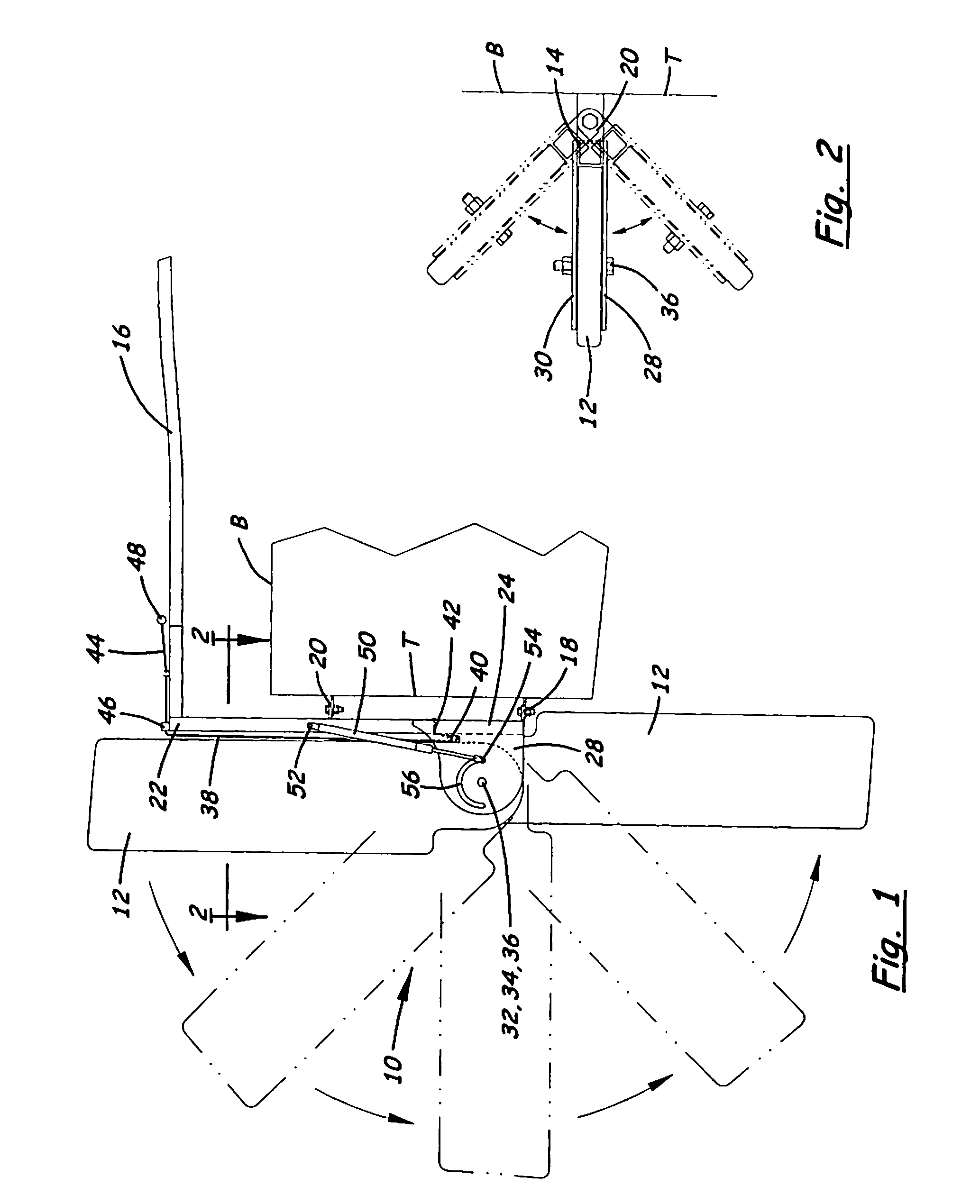
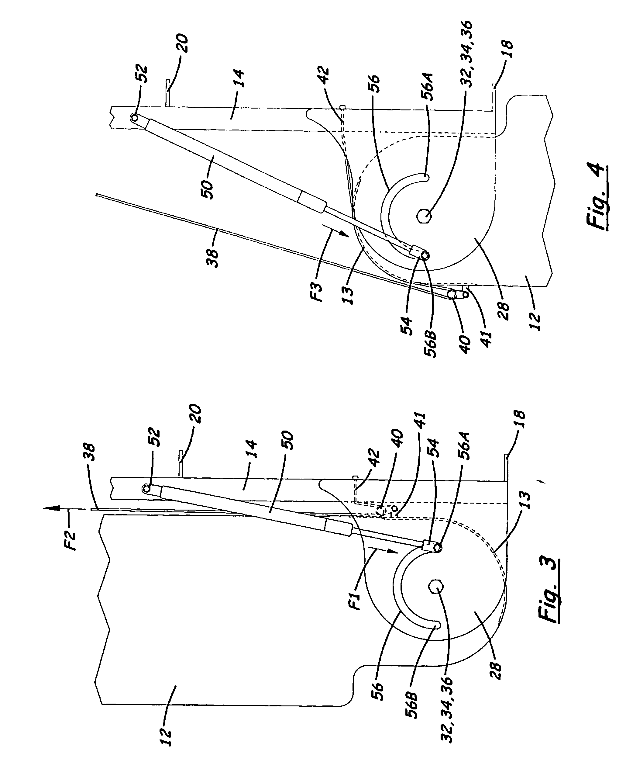
[0021] Until now, the boat industry has seen a long and unresolved need for a retractable rudder system that allows the operator of a boat to raise and lower a rudder with minimal effort and ease, while also allowing the rudder to have a security mechanism that allows the rudder to yield to underwater obstructions.

[0022] The present invention is a retractable sailboat rudder that is moveable from the up or secured position to the down or employed position or from the down to th...


PUM


Abstract

A rudder mechanism for use upon a sailboat is capable of being raised or lowered at the discretion of the boater using a single connected cable operating system, so that the system may be called a “one-pull” system for both raising and for lowering the rudder. The rudder is preferably pivotal, using the cable operating system, greater than 90 degrees, and more preferably, about 180 degrees. A self-contained gas cylinder may aid in the raising and lowering operation and to dampen and smooth the vertical, pivotal movement of the rudder. The cylinder also may be utilized to retain the rudder in a raised or lowered position, once the boater / sailor has purposely placed the rudder in that position, and to return the rudder to the fully-lowered position after grounding has temporarily “kicked-up” the rudder.

Description

CROSS-REFERENCE TO RELATED APPLICATIONS [0001] This application claims the priority date of the provisional application entitled “Sailboat Rudder” filed by Joel F. Santarone on Nov. 3, 2006 with application Ser. No. 60 / 856,418.FIELD OF THE INVENTION [0002] The present invention relates generally to rudder and steering systems for water-born vessels and more particularly to rudder systems for sailboats, wherein the rudder is capable of being raised to a stowed position or lowered to a steering position as required. The preferred embodiment relates to transom-mounted (externally mounted), sailboat “kick-up” rudders that allow upward pivoting of a rudder upon grounding, to help protect the rudder and boat from damage. BACKGROUND OF THE INVENTION [0003] Sailing technology has existed for millennia and there are numerous variations on sailboat rudders. More specifically, there exist numerous sailboat rudders that are retractable in nature. [0004] Retractable rudders are useful for passin...

Claims


Application Information

Patent Timeline
Patent Type & Authority Applications(United States)
IPC IPC(8): B63H25/06
CPCB63H25/06B63H2025/385B63H25/38
Inventor SANTARONE, JOEL F.
Owner SANTARONE JOEL F
Why Eureka
Try Eureka