
Transport retainer

Inactive Publication Date: 2008-05-08
MAGNADYNE CORP
View PDF0 Cites 26 Cited by
  • Summary
  • Abstract
  • Description
  • Claims
  • Application Information

AI Technical Summary

Benefits of technology

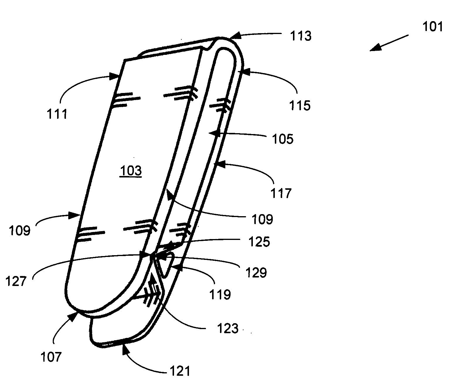
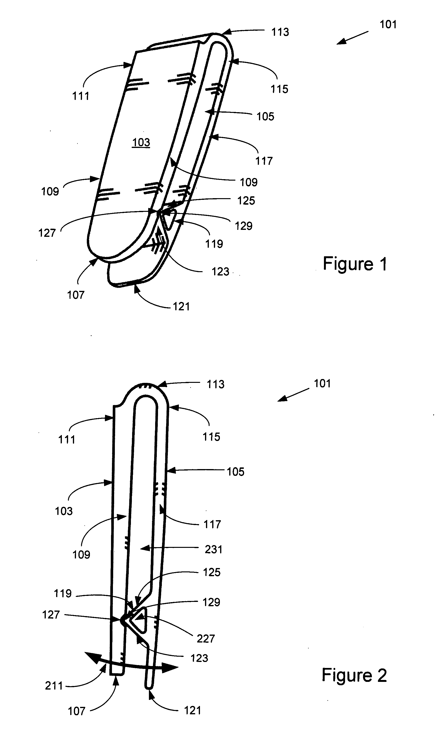
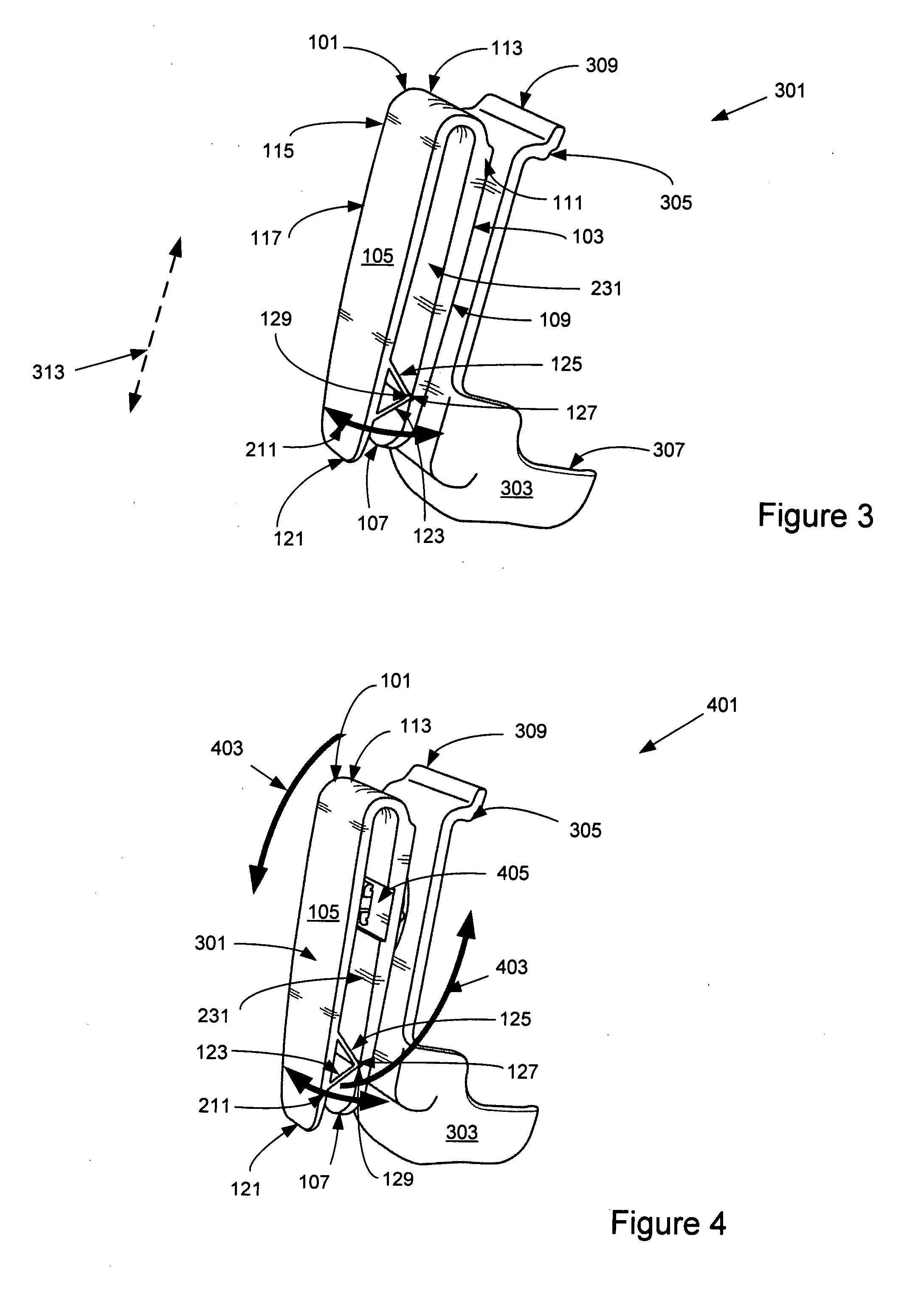
[0008]Accordingly, in operation, the user attaches the retainer to a host object by pushing the retainer onto a host along the exterior slope of the ramp without the user having to initially separate the members and without substantially deforming the host object. With the downward force on the retainer against an object, the force is applied along the exterior slope and thus the object moves up relative to and up the exterior slope until it contacts and pushes the interior of the member opposite the members with the ramp. The applied force continues to push the retainer onto the host object causing the object to temporarily separate the rigid members while the object enters the aperture defined by the interior of the joiner, the interior of the members and the interior slope. As the host object moves through and past the top of the ramp, the joiner urges the top of the ramp to its normally biased resting position against the channel and the object continues to descend through the interior slope and into the aperture. The resilient nature of the joiner, normally biased to its resting position, returns the members to their nominal substantially parallel positions, thus closing the perimeter of the aperture about the host object.
[0009]When the user is ready to remove the retainer from the object, he / she reverses the afore-described process. In the egress the object moves along the interior slope, unseating the ramp from the channel and similarly temporarily separating the members allowing the egress of the host object from the aperture. The bias of the joiner returns the top of the slopes to the matching channel. Accordingly, the retainer is easily placed, securely seated and subsequently removed about a host object without the user having to actively separate the members of the retainer for ingress and egress of the retainer about a host object or substantially deforming the object.
[0010]Moreover, the retainer is configured to carry a PDA with a mating connector attached to or integrally formed on one of the members. A PDA is permanently or selectively attached to and detached from the retainer and the retainer is in turn selectively attached and detached to a host object. As disclosed, the ingress and egress of the retainer, with or without a PDA, onto or from an object is achieved by pushing the retainer, without the user having to actively separate the members.

Problems solved by technology

The challenge, however, is that such retainers are cumbersome.
Namely, they do not provide for simple and prompt ingress and egress of the retainer from the object to which it is attached.
One often frustratingly wrestles with the retainer, especially when the cell phone rings and the user tries to take the PDA out before the call is lost.

Method used


Image

  • Transport retainer
  • Transport retainer
  • Transport retainer

Examples


Embodiment Construction

[0024]Shown in FIG. 1, is a representative embodiment of the disclosed retainer 101. Retainer 101 generally comprises a first member 103 and a second member 105. Members 103 and 105 are substantially rectangular having a width, length and height dimensions. Members 103 and 105 are substantially parallel with respect to each other in their nominal resting position. Although it is foreseeable that the functionality of the disclosed embodiments could be replicated by members 103 and 105 that are not parallel. Member 103 is defined by oppositely disposed, substantially rigid bottom portion 107, top portion 111 and sides 109. Similarly, member 105 is defined by oppositely disposed, substantially rigid bottom portion 121, a top portion 115 and sides 117. It should be also noted that the embodiments throughout this description are described in terms of functional sections. However, the functionality of members 103 and 105 along with joiner 113 could be formed or described as a single devic...


PUM


Abstract

A retainer configured for attachment to objects and for carrying personal appliances such as, but not limited to, a cell phone or a music player. The retainer comprising two members held together in substantially parallel relationship by a unshaped joiner at one end and by a ramp attached to the interior side of one of the members toward the other end. The ramp has exterior and interior slopes converging at the top and forming a compressible male form for fitment into a corresponding female form. The ramp allows ingress and egress of the retainer onto objects that separate the members as the retainer is pushed on and pushed off the object.

Description

CROSS-REFERENCE TO RELATED APPLICATIONS[0001]This application is a continuation in part of U.S. utility application entitled, “Transport Retainer,” having Ser. No. 11 / 592,548, filed Nov. 3, 2006, which is entirely incorporated herein by reference.BACKGROUND[0002]1. Field[0003]The disclosed embodiments relate generally to a retaining device allowing one to carry and easily attach and detach an appliance, such as a cell phone or a PDA (personal digital appliance) to and from another object.[0004]2. Discussion of the Relevant Art[0005]Cell phones are widely proliferated throughout our society. More and more functionality, such as voice, text, photography, calendaring and email access, is being integrated within the cell phone. These units are evolving into portable, handheld devices often referred to as a personal digital appliance (hereafter collectively the “PDA”). Users are used to carrying their PDA's in their pockets, pocket books and generally about their person, allowing them to...

Claims


Application Information

Patent Timeline
IPC IPC(8): A45F5/00
CPCA45F5/02Y10T24/1394A45F2200/0516
Inventor YEH, WEN-TSAN YEH
Owner MAGNADYNE CORP
Learn More