
Axial and Radial Play and Angle Compensation of a Tolerating Pipe Connection

a pipe connection and axial and radial play technology, which is applied in the direction of pipe elements, applications, animal husbandry, etc., can solve the problems of undesirable noise and damage, no radial compensation between the interior part constructed as a sliding ring, etc., and achieve wide elastic sealing, cost-effective production, and favorable effect

Inactive Publication Date: 2008-05-01
FEY LAMELLENRINGE
View PDF15 Cites 3 Cited by
  • Summary
  • Abstract
  • Description
  • Claims
  • Application Information

AI Technical Summary

Benefits of technology

[0004]They can, therefore, easily be retrofitted into existing pipe connections. In addition, because of their conventional metal construction, they are heat-resistant and break-proof and are therefore excellently suitable for sealing a pipe connection with respect to aggressive and high-temperature mediums. As a result, they are advantageous as sealing devices in exhaust pipe connections, particularly with respect to hot engine exhaust gases of temperatures of up to 730° C.
[0021]The ends, which project to the inside or outside with respect to the circular shape, will then have the effect that the double windings are pressed toward the outside or toward the inside in the installed condition. The roundness of the closed double winding over 360 degrees ensures a firm contact with the groove base of the annular groove or with the working diameter.

Problems solved by technology

However, no radial compensation is provided between the interior part constructed as a sliding ring and the exterior part constructed as a slide bush.
The reason is that there is a risk that the connection between the bell part and the interior part, which has radial play because of the required compensating movements, is excited to carry out vibrations such that the bell part impacts on the interior part and thereby causes undesirable noise and damage.

Method used


Image

  • Axial and Radial Play and Angle Compensation of a Tolerating Pipe Connection
  • Axial and Radial Play and Angle Compensation of a Tolerating Pipe Connection
  • Axial and Radial Play and Angle Compensation of a Tolerating Pipe Connection

Examples


Embodiment Construction

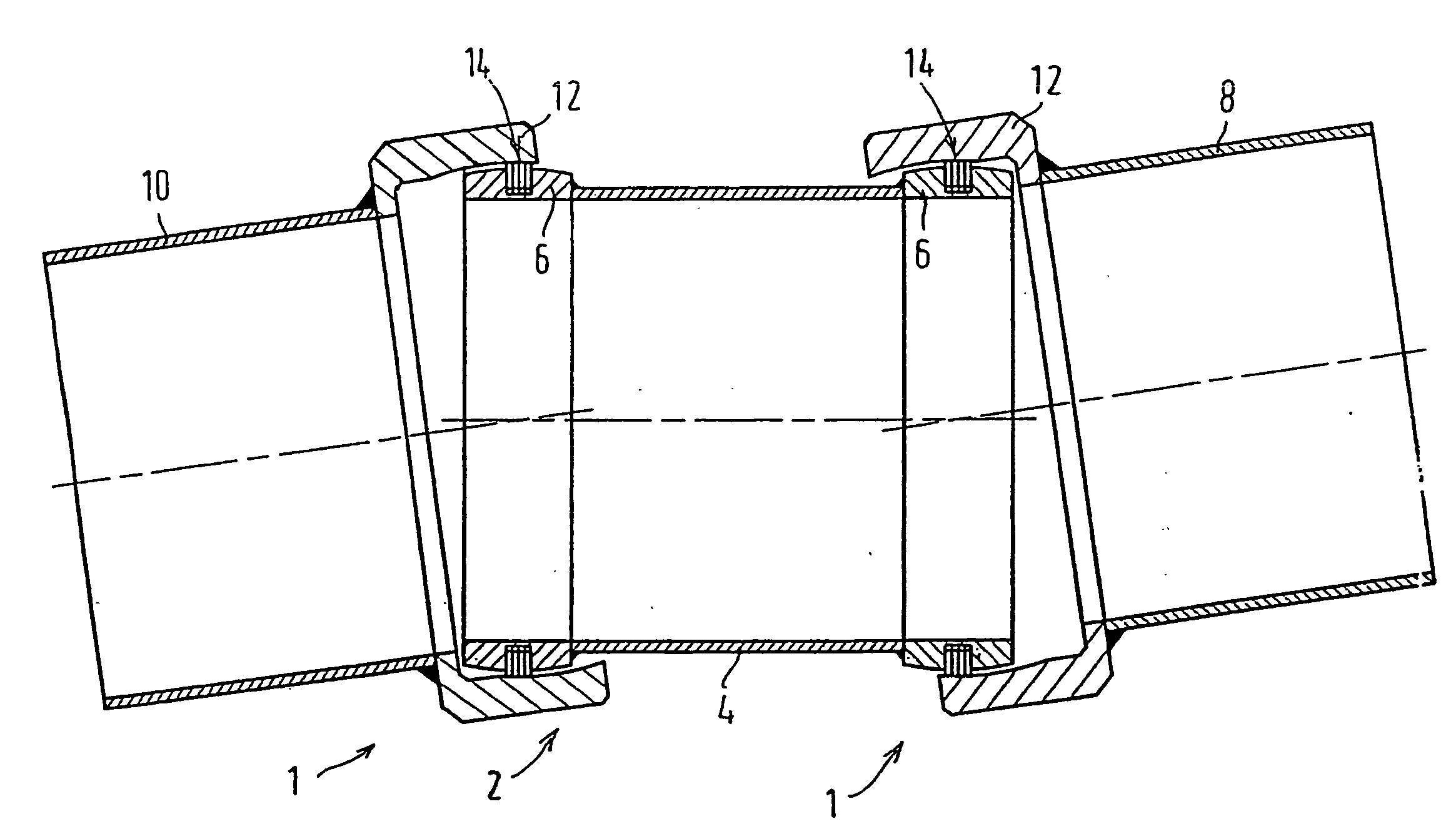
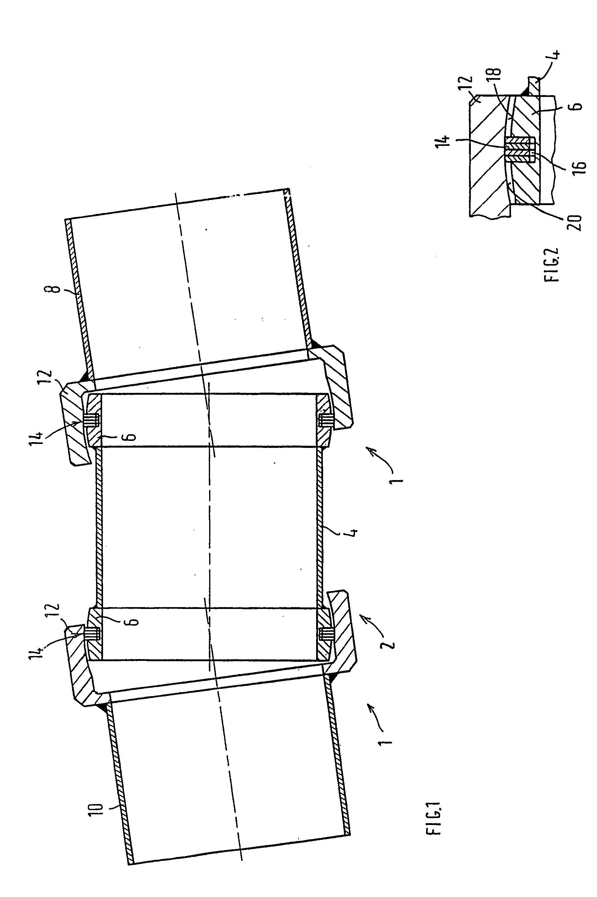
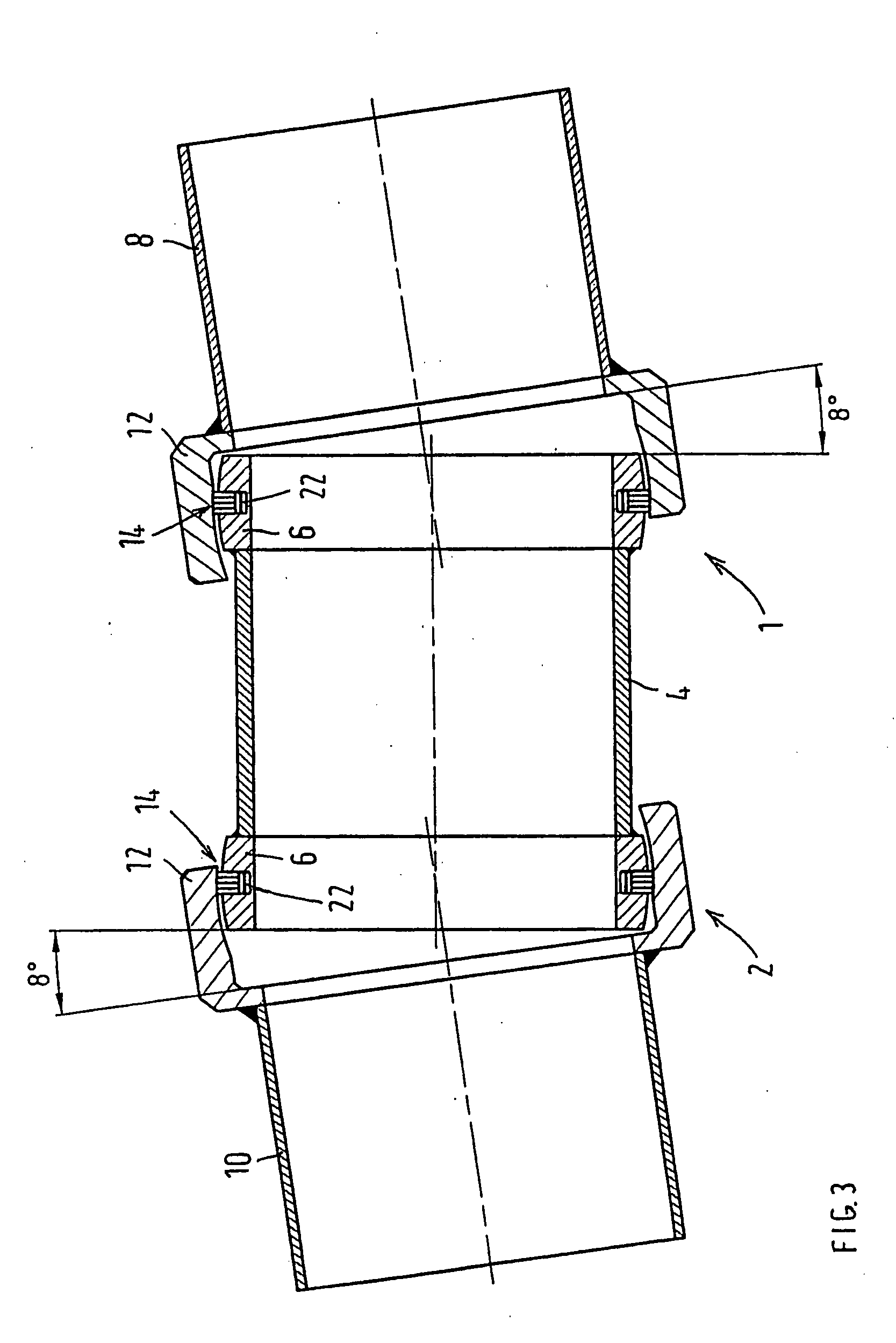
[0030]FIG. 1 illustrates pipe connections 1 of an exhaust pipe of an internal-combustion engine, which tolerate an axial and radial play as well as an angle compensation, according to an embodiment of the present disclosure. The pipe connections 1 are implemented in a double-jointed connection 2, also called “bone” in technical terminology. The double-jointed connection 2 includes an intermediate pipe 4 with interior parts 6 arranged at an end of a side. Interior parts 6 are each surrounded by a bell part 12 arranged at the end on exhaust pipes 8, 10 respectively. The interior parts 6 and / or the bell parts 12 may be produced as separate components and may be fastened to the ends of the exhaust pipes 8, 10 and of the intermediate pipe 4 by, for example, welding. The pipe connections 1 have identical constructions, so that only one of the pipe connections 1 will be described in the following.

[0031]At least one lamellar ring 14, or four lamellar rings, as shown, for example, in FIGS. 1...


PUM


Abstract

The present disclosure is related to a pipe connection for exhaust pipes of internal-combustion engines. The pipe connection includes an axial and radial plug and an angle compensation. The pipe connection further includes a first pipe, a second pipe and an interior part at an end of the first pipe. The interior part is enveloped by a bell part at an end of the second pipe. The pipe connection further includes at least one lamellar ring held in an annular groove in either a) a radially outer surface of the interior part or b) a radially inner surface of the bell part. The at least one lameller ring is tensioned against either a) the radially outer surface of the interior part or b) the radially inner surface of the bell part. Either or both of a) the radially outer surface of the interior part and b) the radially inner surface of the bell part are constructed as a concave surface. The at least one lameller ring is tensioned against the concave surface.

Description

BACKGROUND AND SUMMARY[0001]The present disclosure relates to a pipe connection tolerating or having an axial and radial play as well as an angle compensation. The pipe connection more particularly relates to a pipe connection in exhaust pipes of internal-combustion engines. The pipe connection includes an interior part which is constructed at the end of one pipe and which is enveloped by a bell part at the end of another pipe. At least one lamellar ring is held in an annular groove in the radially outer surface of the interior part or in the radially inner surface of the bell part. The at least one lamellar ring is tensioned against the radially inner surface of the bell part or against the radially outer surface of the interior part. The radially inner surface of the bell part and / or the radially outer surface of the interior part are constructed as a spherical segment surface, which is concave with respect to the lamellar ring, or as a concavely spherical surface. The at least on...

Claims


Application Information

Patent Timeline
IPC IPC(8): F16L25/12F16L27/00A01K7/02A01K7/06
CPCA01K7/027F16L27/073A01K7/06
Inventor HOLZHEU, PETER LUDWIG
Owner FEY LAMELLENRINGE
Learn More