Identification device for objects with a transponder and a corresponding method

a technology of identification device and transponder, which is applied in the direction of transmission, indirect connection of subscriber, sensing record carrier, etc., can solve the problems of affecting the identification capacity of objects, affecting the identification capacity, and only working mode, so as to increase the identification capacity and increase the identification capacity

Inactive Publication Date: 2008-04-24
DATAMARS
View PDF12 Cites 11 Cited by
  • Summary
  • Abstract
  • Description
  • Claims
  • Application Information

AI Technical Summary

Benefits of technology

[0016]It is particularly advantageous if the transmitting and receiving device is set up so that the antennas may be operated in the multiplexer mode. Such a method is also called multiplexing procedure. This procedure not only allows making optimum use of the electronics, but it also allow minimizing the overlap of the various antenna / transponder interactions. In order to achieve an optimum temporal separation between the measurements carried out with the various antennas, it is advantageous that the antenna planes within the tunnel have a distance of at least 10 mm and that the first plane be preferably parallel to the transport direction of the conveyor band.
[0019]Passive transponders are usually activated by receiving a signal from the antenna, whereby the transponders are first loaded with power from the energy of the antenna and then send off their identification code. It is a substantial advantage for the identification device if the latter and the transponders are set up so that upon identification of each transponder it commands said transponder to switch into a mode (“quiet mode”) in which the transponder does not respond during the reception of signals from the antenna, usually for as long as the transponder is located in the antenna field and thus is supplied with power therefrom. The command for such a mode can be obeyed by the transponder for as long as it can remember it, which stops to be the case upon leaving the antenna field. However, this can be improved if the transponder has a mode optimized for the identification device (“quiet storage mode”), in which the transponder does not respond not only during the reception of signals, but also for a predetermined time thereafter. For this purpose the transponder needs to have a power supply with a corresponding storage capacity, thus allowing maintaining the optimized mode for a certain time. This time is determined by the energy capacity of the transponder and should correspond approximately to the transit time through the tunnel, which lies in the range of a few minutes.
[0021]If in certain container loads one cannot rule out that two or more transponders will be so close to each other that they cannot be identified, it can be advantageous if the conveyor device is set up in such way that the arrangement of transponders can be changed during the reading process by means of a non-linear movement profile—preferably by means of a shaking movement—e.g. transversally to the transport direction, so as to increase the number of identifiable transponders upon passing onto the conveyor band.

Problems solved by technology

In doing so, a variety of difficulties arise.
Obviously, with a purely passive transponder this operating mode only works as long as the transponder is supplied with power.
Indeed, further problems arise because the H-field antennas that necessarily are used by the reading device—usually coils that are brought close to the ensemble, cannot interact with any transponder antennas whose coil plane is perpendicular to or forms a large angle with the coil plane of the antenna coils of the reading device.
Particularly the antenna that is not arranged around the tunnel has turned out to be disadvantageous since it is not able to contribute much in identifying the transponders.
An arrangement that is very similar to the crossed antenna arrangement is known from JP-A-2004 / 192223, which, however, does not offer any further advantages for solving the problems that arise.
These antennas cannot contribute much to the solution of the above mentioned problem.
Moreover, there are two further antennas surrounding the tunnel which are of the type already recognized to be disadvantageous in the above described arrangement, which antennas are at a certain angle and form an approximately linearly independent system, the coils of the two antennas even overlapping each other at one side thereof.
Although this solution comprises a large number of antennas, it cannot solve the problem described hereinbelow.
In fact, a further problem is known, namely the presence of two or more transponders in close proximity to each other, which mutually interfere even when they are not aligned in the same direction.

Method used


Image

  • Identification device for objects with a transponder and a corresponding method
  • Identification device for objects with a transponder and a corresponding method
  • Identification device for objects with a transponder and a corresponding method

Examples


Embodiment Construction

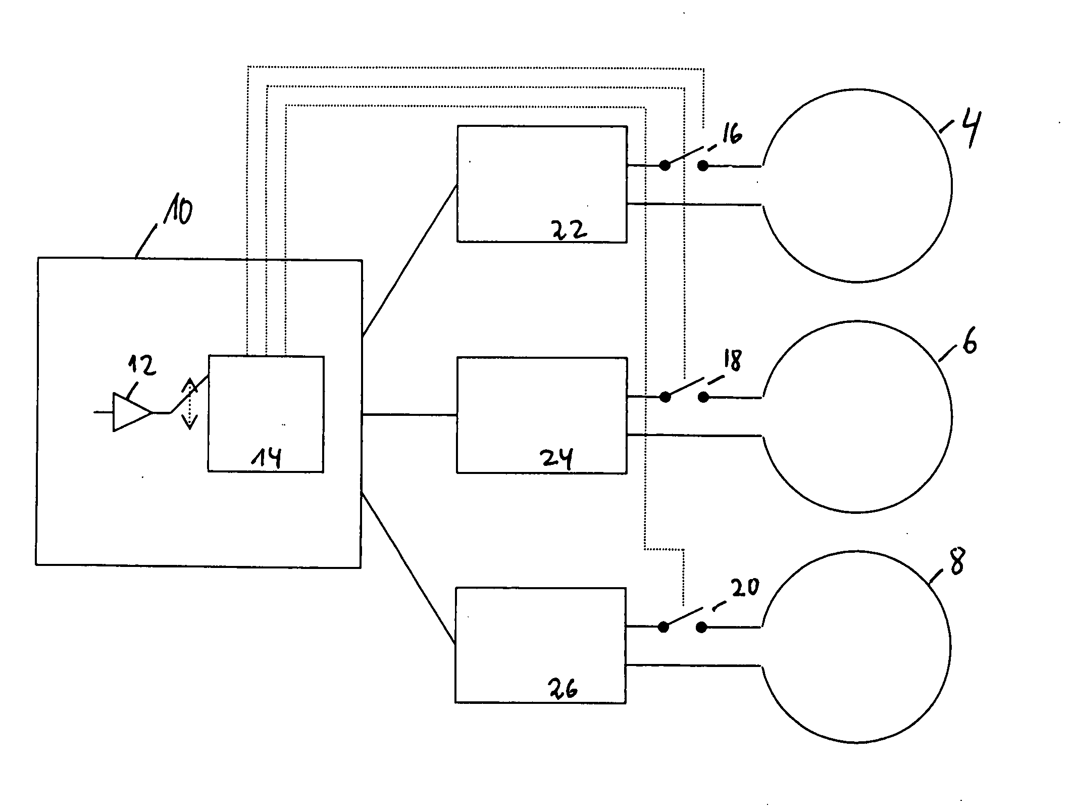
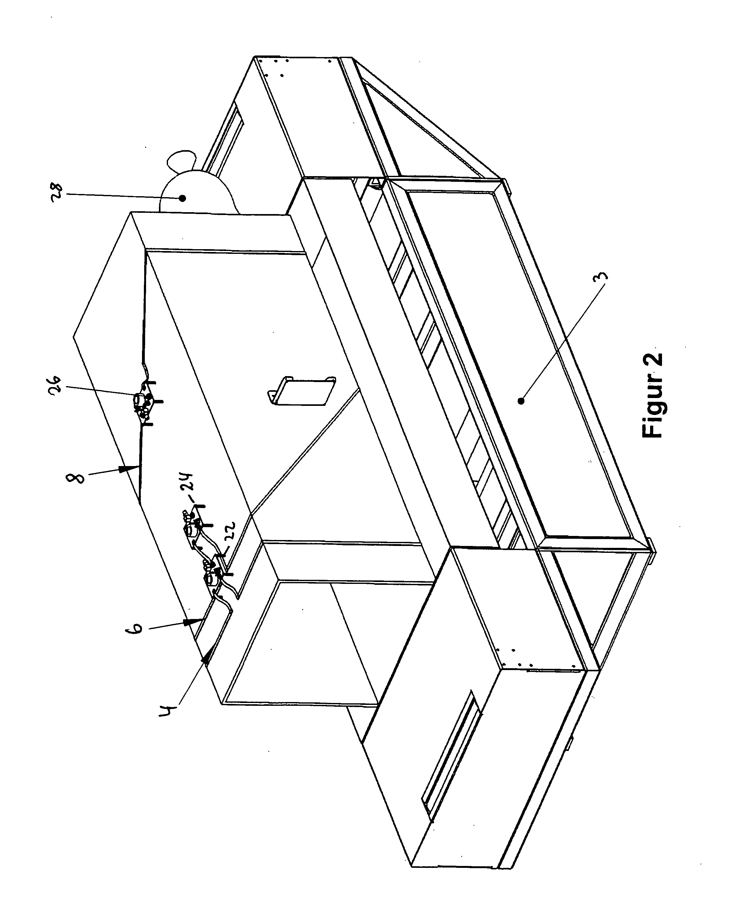
[0031]In an embodiment, the tunnel denoted as 2 in FIGS. 1 to 3 is provided with three antennas 4, 6 and 8 which are laid out as coils around the tunnel. On the bottom surface of tunnel 2 there is arranged conveyor device 3, namely a transport band for the transport containers containing the objects provided with transponders. In FIG. 2 the identification device is shown without the shielding 11 shown in FIG. 1, so that the tuning devices 22, 24 and 26 can be seen.

[0032]The normal of the plane of the first antenna 4 is parallel to the transport direction x of the conveyor band, and this direction is indicated as x′ in FIG. 1. In the present embodiment the first antenna 2 coincides with the tunnel entrance. The second antenna 6 is tilted (vertically) with respect to the first antenna 4 by an angle of about 45°. The normal of its plane is indicated as y′ in FIG. 1. An important feature of the present embodiment is that the center of the second antenna 6 lies approximately in the middl...


PUM


Abstract

In order to achieve an optimal identification with an identification device for objects that comprise a transponder and are transported by means of a conveyor device through a closed tunnel (2), it is proposed that the antenna device of the transmitting and receiving device (10) comprises at least three sequentially arranged coil-shaped antennas (4, 6, 8). They surround the tunnel (2), each lying in a plane and representing a linearly independent system. The antennas (4, 6, 8) are operated in a multiplexer mode.

Description

[0001]This application claims priority of application EP 06 022 015 having a priority date of Oct. 20, 2006, the disclosure of which is hereby incorporated by reference.FIELD OF THE INVENTION[0002]The invention relates to an identification device for objects with a transponder, with a conveyor device for the objects to be identified as well as to a corresponding identification method.BACKGROUND OF THE INVENTION[0003]In general, a transponder is understood to be a communication element that receives incoming signals and responds thereto. Thus, the term “transponder” is made up of the English terms “transmitter” and “responder”. Transponders can be passive or active.[0004]Passive transponders are systems that draw the power required for communication and for executing internal processes exclusively from the field of the recording / reading unit. Therefore, passive transponders operate without self-power. In contrast, active systems have their own power supply, frequently in the form of ...

Claims


Application Information

Patent Timeline
IPC IPC(8): H04B7/00
CPCG06K7/10435G06K7/10336
Inventor DOMENICO, MAURO DIBRILLI, NICOLA
Owner DATAMARS
Why Eureka
Try Eureka