
Device and method for detecting battery voltage level

a battery voltage and detection method technology, applied in the field of detection of battery voltage levels, can solve the problems of jacking up the hardware cost, affecting the performance of portable electronic devices, so as to avoid misjudgment and accurately detect battery voltage levels

Inactive Publication Date: 2008-04-24
PREMIER IMAGE TECH
View PDF5 Cites 22 Cited by
  • Summary
  • Abstract
  • Description
  • Claims
  • Application Information

AI Technical Summary

Benefits of technology

[0007]It is therefore one object of the present invention to provide a device and an associated method for detecting battery voltage levels, which can accurately detect the battery voltage level and thus avoid misjudgment by the protective mechanism of the electronic device.
[0008]Another object of the present invention is to provide a device and an associated method for detecting battery voltage levels, which can make use of an analog-to-digital (A / D) converter or digital-to-analog (D / A) converter included in the digital signal processor of the electronic device to perform detection, thereby saving the cost of hardware.
[0009]Another object of the present invention is to provide a device and an associated method for detecting battery voltage levels, which allows flexible setting of voltage reference levels for detection without need to adjust hardware circuit.

Problems solved by technology

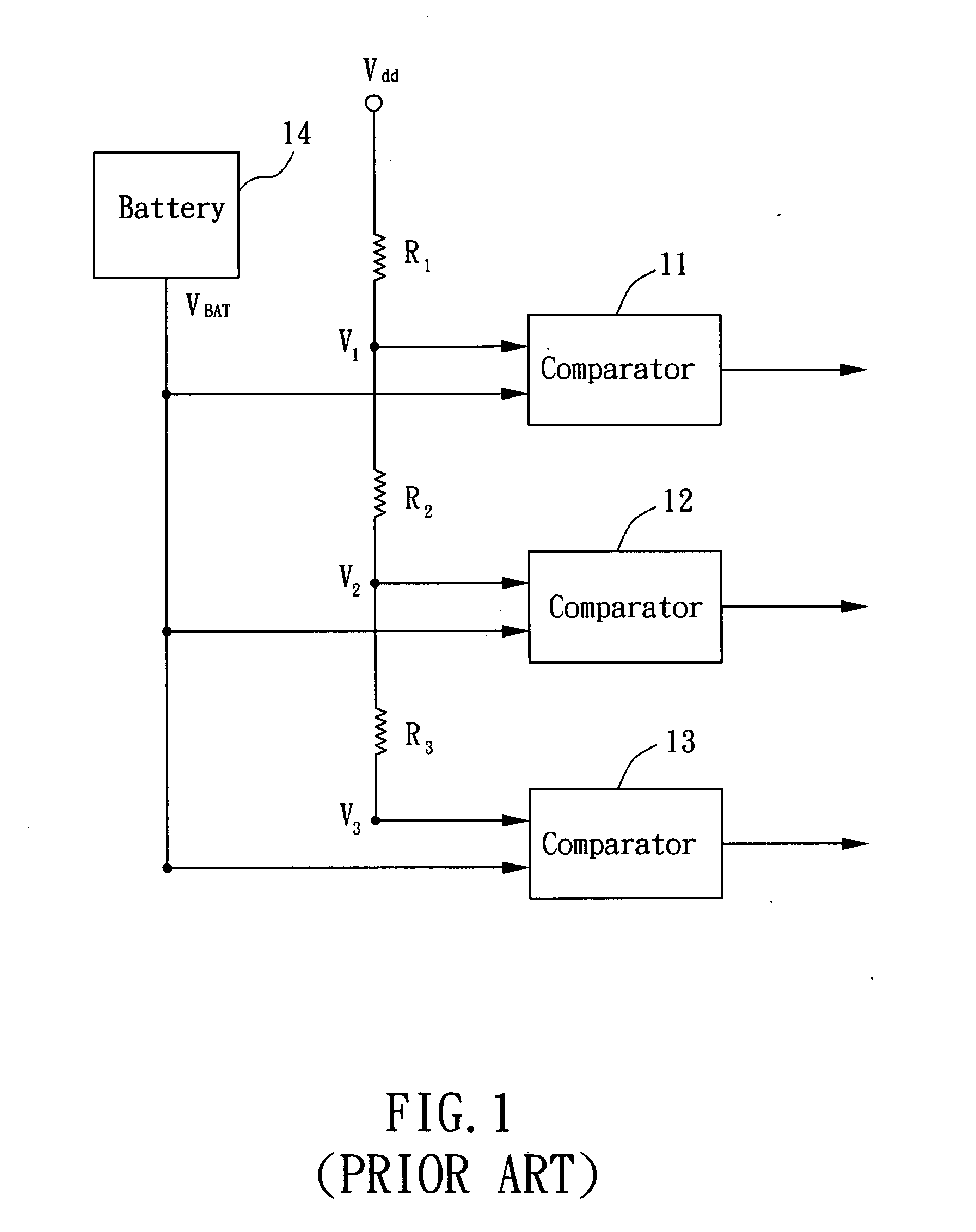
However, the circuit in FIG. 1 needs to use multiple comparators and voltage dividing resistors which jacks up the cost of hardware.
In addition, to produce precise reference levels, the voltage dividing resistances must be under precise control, which is difficult in practice since the resistance value is subject to the influence of process, temperature, and other factors.
Thus the circuit in FIG. 1 is hardly able to precisely detect the battery voltage level, and also affects its ability to make a correct judgment as to whether the battery voltage has fallen below the minimum allowable level such that early or late activation of the protective mechanism might occur.
As a result, the performance of the portable electronic device is affected or its components might be damaged.
In addition, in the circuit of FIG. 1, the adjustment of reference levels can only be achieved by adjusting the hardware circuit (e.g. changing the voltage dividing resistance), which is quite an inconvenience in practice.

Method used


Image

  • Device and method for detecting battery voltage level
  • Device and method for detecting battery voltage level
  • Device and method for detecting battery voltage level

Examples


first embodiment

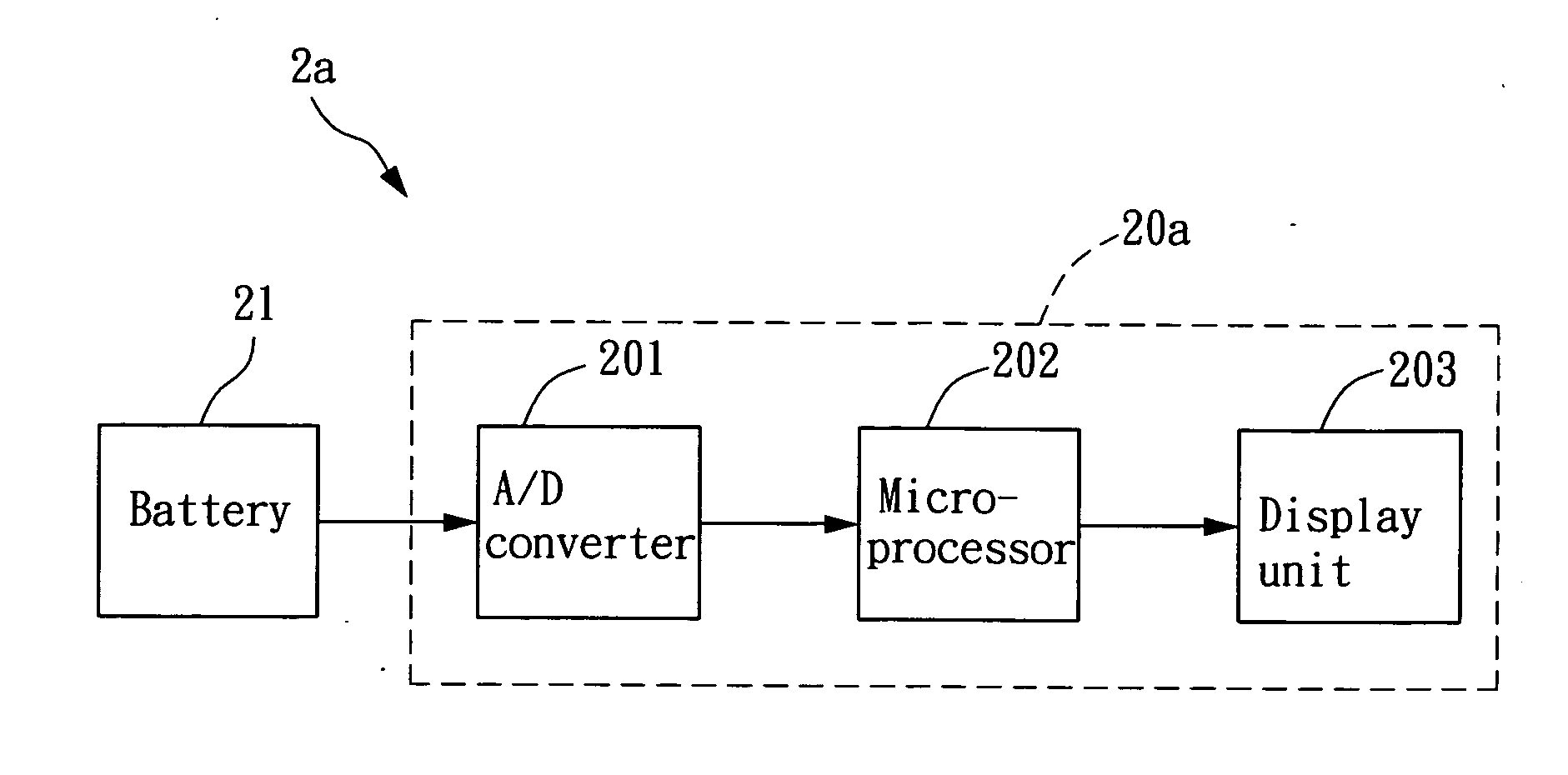
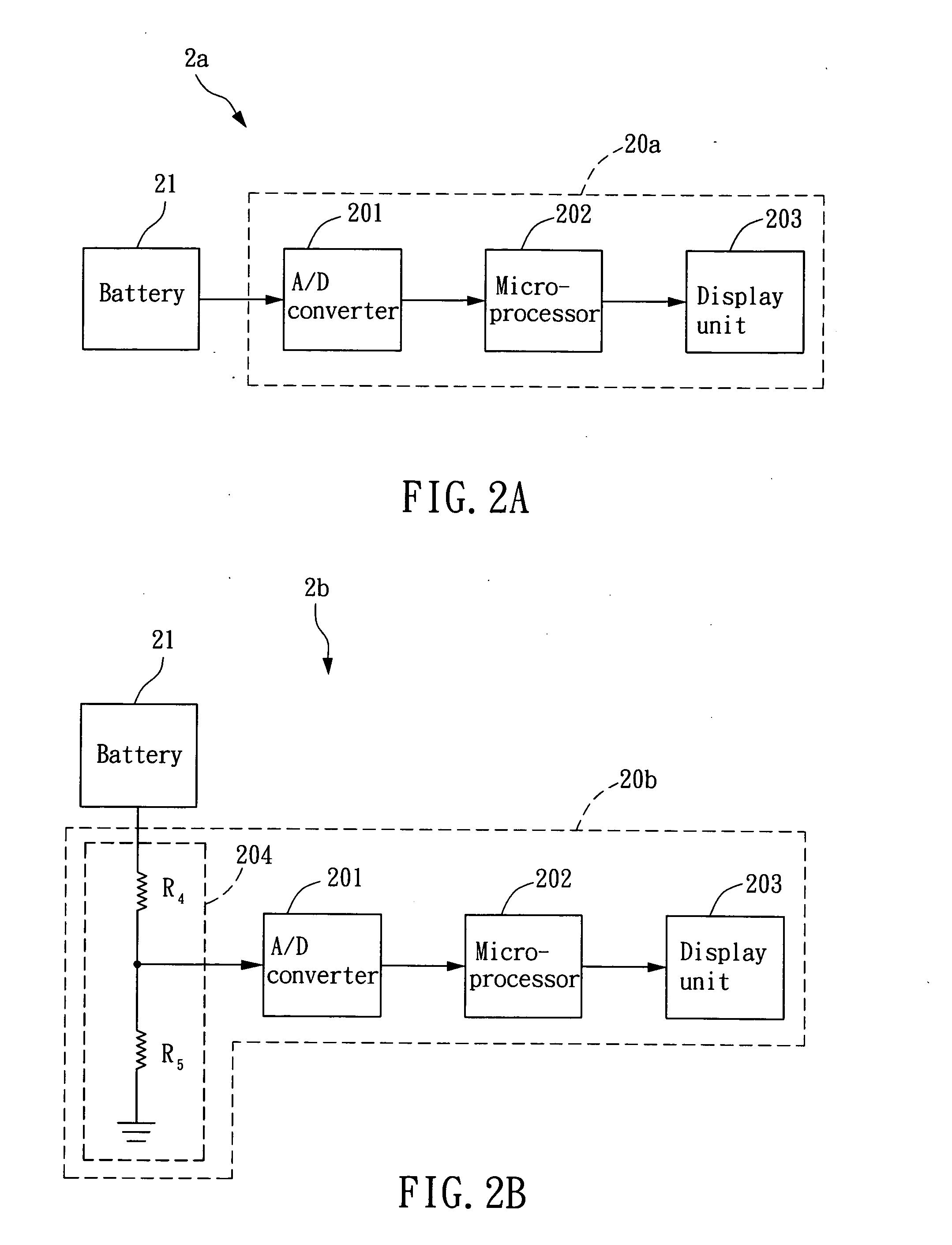
[0019]FIG. 2A is the diagram of a battery voltage level detection device according to the invention. The detection device 20a is included in an electronic device 2a and comprises an analog-to-digital (A / D) converter 201, a microprocessor 202, and a display unit 203. The A / D converter 201 is coupled to a battery 21 of the electronic device 2a and converts an analog voltage signal output by the battery 21 to a corresponding digital signal. The microprocessor 202, coupled to the A / D converter 201, determines the current voltage level of the battery 21 according to the digital signal, and outputs a corresponding level signal to the display unit 203. The microprocessor 202 may determine the voltage level of the battery 21 by executing a firmware program. Moreover, if the microprocessor 202 determines that the voltage level is below a threshold, it will activate a protective process of the electronic device 2a, such as automatic shutdown or entering a standby mode. The threshold is the lo...

second embodiment

[0021]FIG. 2B is the diagram of a battery voltage level detection device according to the invention. In FIG. 2B, detection device 20b is included in an electronic device 2b. In comparison with detection device 20a in FIG. 2A, the detection device 20b contains in addition a voltage dividing circuit 204 which is coupled between battery 21 and A / D converter 201 and outputs a voltage dividing signal to the A / D converter 201 according to the output voltage of battery 21. The A / D converter 201 then converts the voltage dividing signal into a corresponding digital signal. The remaining operation in FIG. 2B is similar to that in FIG. 2A and will not be elaborated here. The addition of the voltage dividing circuit 204 in FIG. 2B takes into consideration that the output voltage of battery 21 might exceed the acceptable limit of A / D converter 201 under certain circumstances. The voltage dividing circuit 204 can lower the voltage level inputted into the A / D converter 201 to circumvent the afore...

fourth embodiment

[0026]FIG. 4 is a flow chart showing the method for detecting a battery voltage level according to the invention. This detection method is applied to an electronic device, which comprises a battery and a digital signal processor. The digital signal processor further comprises an A / D converter and a microprocessor. As shown in FIG. 4, the detection method includes the following steps:

[0027]Step 41: Convert the output voltage of the battery into a corresponding digital signal;

[0028]Step 42: Determine the current voltage level of the battery according to the digital signal;

[0029]Step 43: Output a level signal according to the determined voltage level;

[0030]Step 44: Display the determined voltage level according to the level signal; and

[0031]Step 45: Activate a protective process of the electronic device if the determined voltage level is below a threshold.

[0032]Step 41 is carried out by the A / D converter. Step 42 is performed by the microprocessor via the execution of a firmware progra...


PUM


Abstract

A device and an associated method for detecting a voltage level of a battery are disclosed. The device employs an analog-to-digital converter or digital-to-analog converter to accurately detecting the voltage level. In one embodiment, the device includes a digital-to-analog converter, a comparison circuit, and a microprocessor. The digital-to-analog circuit outputs a plurality of reference levels according to a setting signal. The comparison circuit is for comparing the output voltage of the battery with the reference levels and outputting a comparison signal. The microprocessor then determines the voltage level of the battery according to the comparison signal.

Description

BACKGROUND OF INVENTION[0001]1. Field of the Invention[0002]The present invention relates to the detection of battery voltage levels, and more particularly to a device and an associated method for detecting the battery voltage level by using an analog-to-digital converter or digital-to-analog converter.[0003]2. Description of the Prior Art[0004]The battery is an indispensable component of portable electronic devices, such as digital camera, notebook PC and mobile phone. The output voltage level of the battery would drop as the battery ages. In light that electronic components might be damaged by the insufficient voltage provided by the battery, portable electronic devices are typically designed with a protective mechanism (e.g. automatic shutdown), which is activated when battery voltage falls below a minimum allowable level, to prevent damage to the electronic components.[0005]FIG. 1 shows the diagram of a conventional battery voltage detection circuit, which generates three refere...

Claims


Application Information

Patent Timeline
IPC IPC(8): G01R19/25
CPCG01R31/3648G01R31/362G01R31/3835
Inventor HUANG, YU LIN
Owner PREMIER IMAGE TECH
Learn More