
Dust-collecting auxiliary device for vacuum cleaner

Inactive Publication Date: 2008-04-24
GUTEN ELECTRONICS INDAL
View PDF21 Cites 6 Cited by
  • Summary
  • Abstract
  • Description
  • Claims
  • Application Information

AI Technical Summary

Benefits of technology

[0007]The present invention has been accomplished under the circumstances in view to provide a dust-collecting auxiliary device that facilitates enhancing dust-collecting efficiency of a vacuum cleaner.
[0009]Thus, the object of the present invention to provide a dust-collecting auxiliary device utilizing airflow blew form the air pipe to congregate dust or trash toward the suction inlet. Additionally, the two wings enlarge the dust-collecting area of the suction inlet suction inlet and facilitate converging airflow blew form the air pipe toward the suction inlet so that dust and trash in said dust-collecting area can be sucked through the suction inlet efficiently an smoothly due to the aid of the air pipe and wings.

Problems solved by technology

However, the improvement in suction of such a disk-shaped vacuum cleaner may be limited by because the reduced volume thereof may not sufficient to accommodate a larger and powerful motor and the suction inlet thereof is not designed to be fixed an irreplaceable.

Method used


Image

  • Dust-collecting auxiliary device for vacuum cleaner
  • Dust-collecting auxiliary device for vacuum cleaner
  • Dust-collecting auxiliary device for vacuum cleaner

Examples


Embodiment Construction

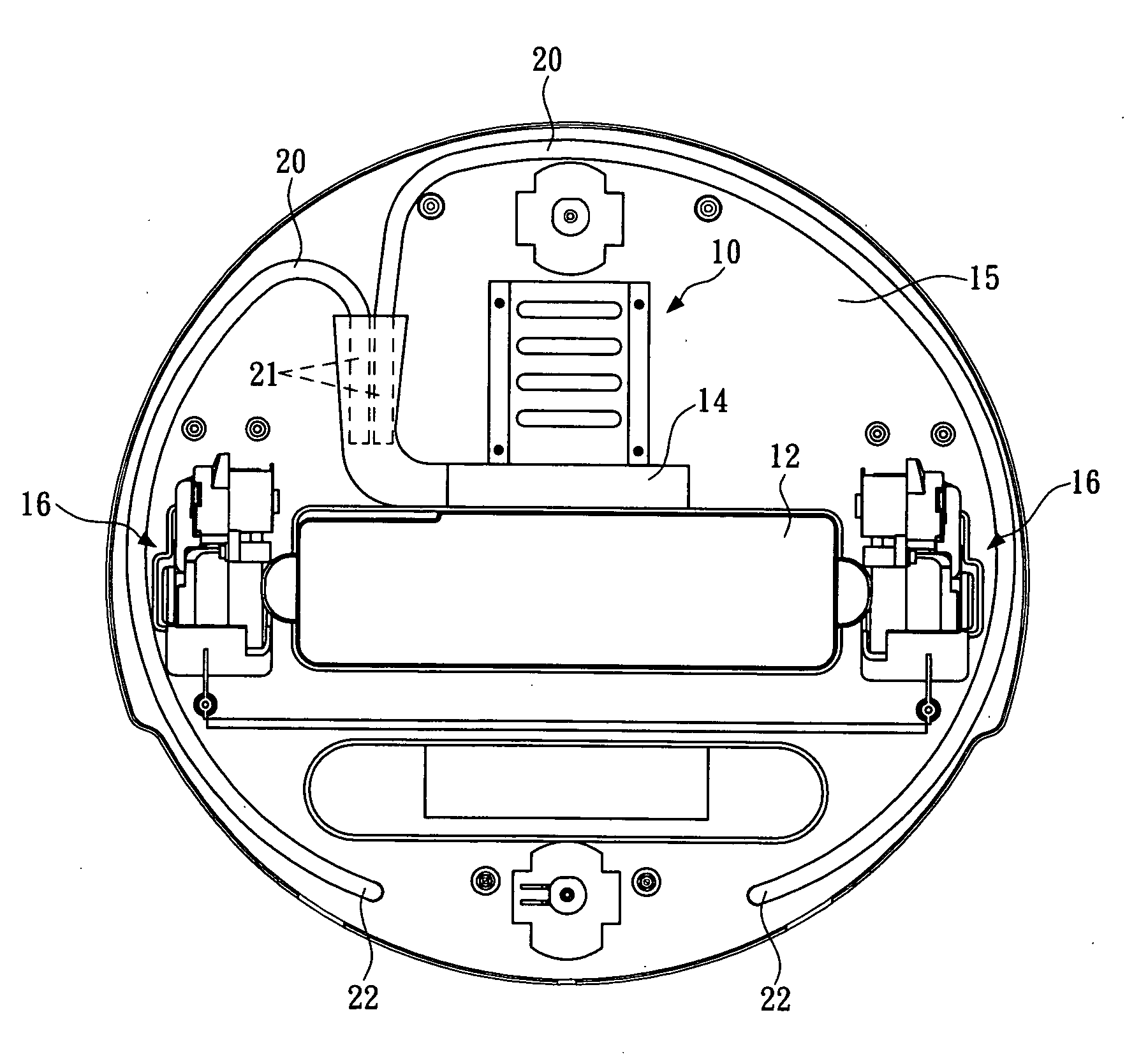
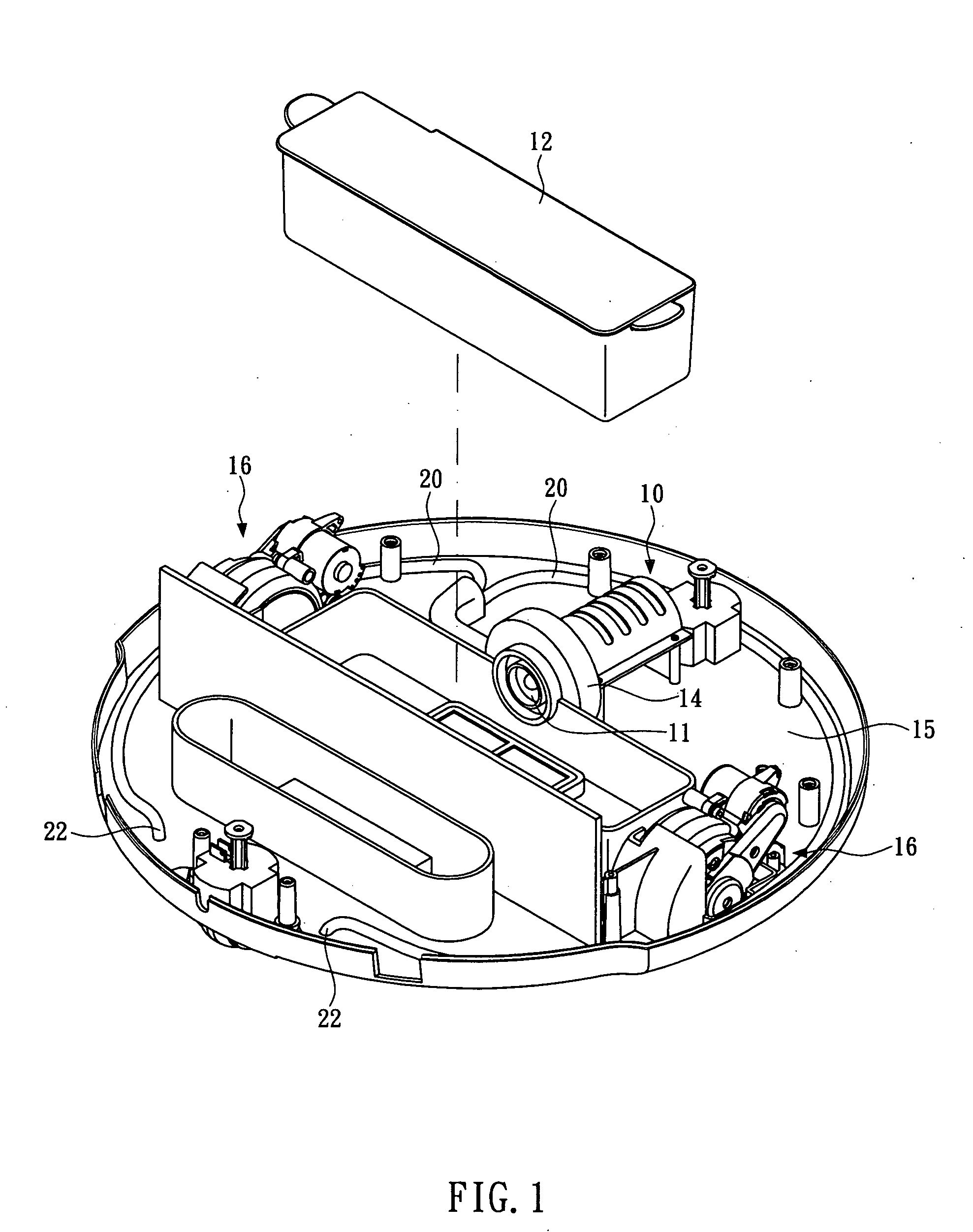
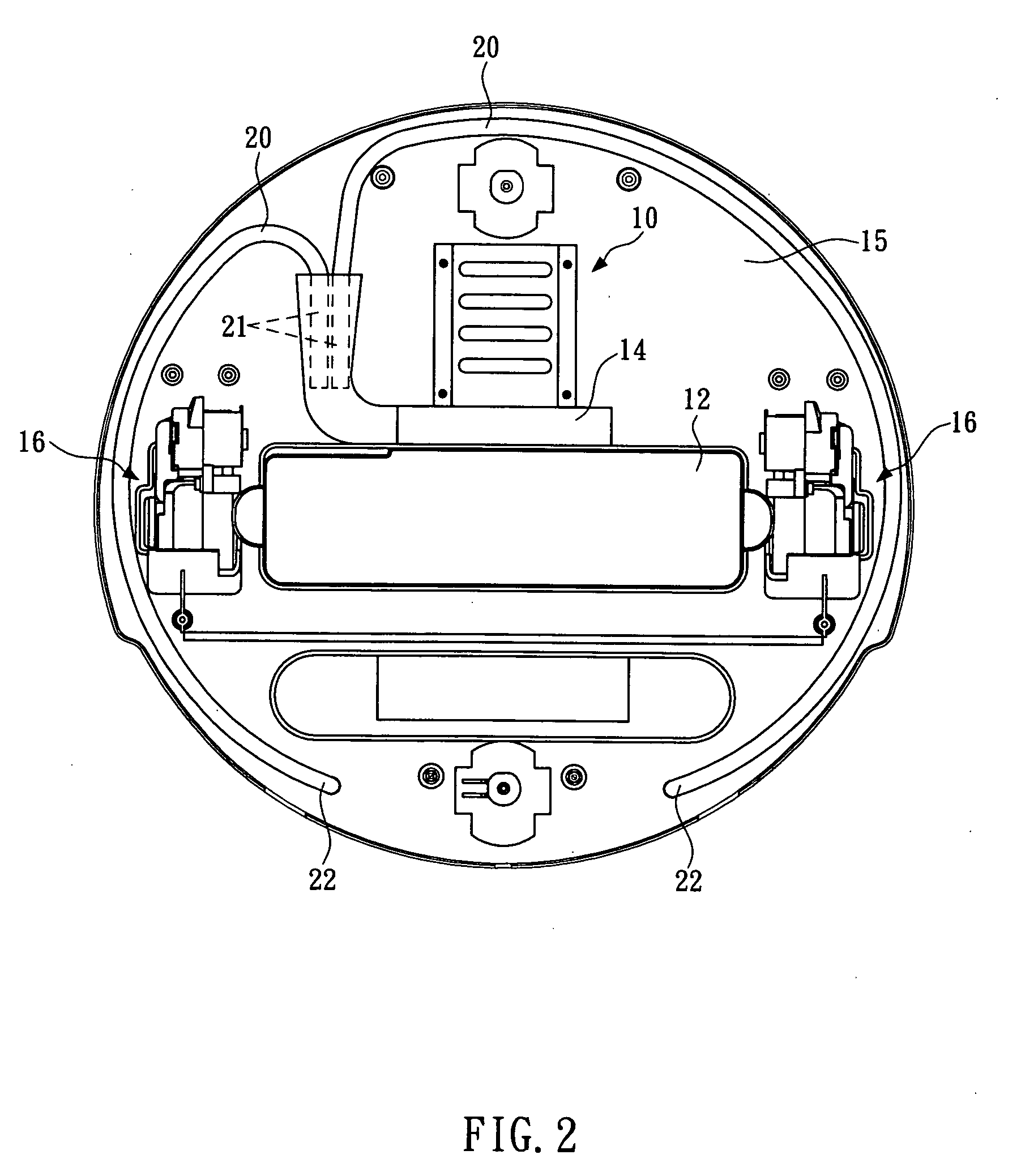
[0015]As a modern disk-shaped vacuum cleaner according to the present invention is schematically shown in the Figures, those details not related to the essentials of the present invention are not accounted herein. In the Figures, a motor 10, a fan 11, a dust-collecting chamber 12, a suction inlet 13 and a driving device 16 of prior art are disclosed, wherein the driving device 16 drives the vacuum cleaner moving automatically; the motor 10 rotates the fan 11 to generate suction which passes through the dust-collecting chamber 12 and sucks up external air, dust and trash at the suction inlet 13; and retains dust and trash in the dust-collecting chamber 12.

[0016]For improving dust-collecting ability of such a vacuum cleaner, the present invention provides a dust-collecting auxiliary device which is composed of two air pipes 20 and two wings 25 as shown in FIGS. 1 to 5.

[0017]Each of the air pipes 20 is a flexible tube, of which an inlet 21 at one end is fixed in a fan container 14 encl...


PUM


Abstract

A dust-collecting auxiliary device is equipped on a vacuum cleaner that comprises at least a motor, a fan, a dust-collecting chamber, a suction inlet, and a driving device. Said dust-collecting auxiliary device includes at least one air pipe of which an air inlet at one end is fixed in a fan container of said fan and an air outlet is placed at the lower surface of the bottom cover of the vacuum cleaner in to the neighboring-front the suction inlet, at least two wings wherein each wing with one end fixed at the one side of the suction inlet, while the other end thereof extended forward and outward to give an increasing distance from another wing.

Description

BACKGROUND OF THE INVENTION[0001]1. Technical Field[0002]The present invention relates to vacuum cleaners and, more particularly, to a dust-collecting auxiliary device that improves the dust-collecting efficiency of a vacuum cleaner.[0003]2. Description of Related Art[0004]A typical vacuum cleaner primarily comprises a motor, a fan, a dust-collecting chamber and a suction inlet, wherein the motor drives the fan to create suction which passes through the dust-collecting chamber and sucks up external air, dust and trash at the suction inlet. As the collected air, dust and trash are drawn into the dust-collecting chamber, which possess reduced pressure due to the relatively large internal space, dust and trash which are relatively heavier than the air are retained in the chamber, while the air is successively filtered through a filter before exhausted from the cleaner at an exhaust.[0005]Varied technical means for improving dust-collecting efficiency for various vacuum cleaners has bee...

Claims


Application Information

Patent Timeline
IPC IPC(8): A47L9/02
CPCA47L5/14A47L5/28A47L2201/00A47L9/0686A47L9/08A47L9/06
Inventor LIAO, BEEN-TZAW
Owner GUTEN ELECTRONICS INDAL
Learn More